BMF
contributing
Posts: 99 
|
Post by BMF on Apr 23, 2013 23:59:12 GMT
Looks like Frans' circuit is for Mono, so that's the way I will go. Makes sense, too, since the other channel in my present phantom power supply gets no love. Keith, will you be wiring this up for a single-mic setup or one mic per ear? My current kit has a stereo one-mic-per-ear setup. But I found that the mics measured slightly differently. So I took two or three measurements in both ears, then swapped the mics around and took another two or three measurements. Then averaged the per-ear measurements out. It was inconvenient, but it gave me some sense of the variability caused by mics and mic placement. Not sure which way I'd go if I were to redo my setup.... |
|
solderdude
Administrator
measureutternutter
Posts: 4,882
|
Post by solderdude on Apr 24, 2013 6:36:17 GMT
For stereo... build 2 of them and connect the +9V of the circuits and the ground (common) of the circuits.
|
|
BMF
contributing
Posts: 99
|
Post by BMF on Apr 24, 2013 12:43:42 GMT
For stereo... build 2 of them and connect the +9V of the circuits and the ground (common) of the circuits. Thanks for that tip, Frans. BTW, has anyone tried FuzzMeasure? The CSD's are much better than REW. I think you can try a limited version, free for 2 weeks. It's fully functional but you cannot save the graphs within the program. A work-around is to take and save screen shots. I bought it last year, after already completing Incremental Mods and Measurements. I'm going to try it, again, and compare to REW for Windows IF my old Dell PC still works! |
|
BMF
contributing
Posts: 99
|
Post by BMF on Apr 25, 2013 13:58:02 GMT
Frans, Thank you for the information. I think I can source the 6.8k and 8.2k resistors. So, Carbon Film resistors are O.K. for use in your Improved Phantom Power Supply, or are metal film resistors better? I think I'll go ahead and use the 4.7 uF electrolytic caps from Radio Shack and keep the Active Filter BOM intact. I'm considering using FuzzMeasure in place of REW. FuzzMeasure has a Loop Back connection for the "non-measuring channel" that Auto Corrects for time delay/distance. Chris aka SuperMegaUltraGroovy (SMUG) who designed the program recommends the ART USBPRE preamp. It allows for the loop back connection but it provides 48 volts phantom power. I wonder if it would work to install a resistor between the ART USBPRE phantom power and the Panasonic mic that can only handle up to 10 volts? Alternatively, I wonder if there is a way to make the loop connection, bypass the ART USBPRE's phantom power supply, and use your DIY phantom power supply? I emailed Chris and asked him if he knows of a viable work-around or other pre-amp with < 10 volts phantom power. FuzzMeasure looks like a very good program. mrspeakers uses it with a calibrated "wand" microphone that uses 48 volt phantom power. I want to continue using my Dummy Organic Head (DOH!) since I have a lot of experience with this method. I will continue to try and make my wooden Dummy Head work. I've thought about buying an ear (large one for circumaural headphones) to mount on the wooden board described here: www.gras.dk/00012/00058/00166/00344/ and here: www.head-fi.org/t/632286/aes-2012-paper-relationship-between-perception-and-measurement-of-headphone-sound-quality/45I made a crude ear/pinna using Newplast and put it on my wooden dummy board. It improved the graphs such that they look more like my measurements made with the mic in my ear. I am open to changing the BOM to build a better mousetrap. Do you have one you would recommend, with a schematic? I'm using 3.5 mm TRS jacks and RCA plugs.  The upper schematic is for usage with non-polar capacitors. The bottom one is for usage with much cheaper electrolytic caps. Beware of the polarity of the used electrolytic capacitors. For the jack plug in the schematic the output is connected to the R channel (ring) but you can also connect it to the tip (Left channel) OR both channels (L + R). Some mic inputs have the R (ring) and ground connected. In that case the signal must go to the tip connection and the ground is the same.
NOTE: The mic connection that must be connected to ground has a small trace from the pad to the metal casing. The connectors shown are simply suggestions as to how to wire the most common connectors. You should connect only the connector type you need to use, so not both connectors. 6k8 = 6.8k (just a different way of notation) |
|
solderdude
Administrator
measureutternutter
Posts: 4,882
|
Post by solderdude on Apr 25, 2013 15:27:41 GMT
So, Carbon Film resistors are O.K. for use in your Improved Phantom Power Supply, or are metal film resistors better? For this application and position in the schematic it doesn't matter at all. I'm considering using FuzzMeasure in place of REW. FuzzMeasure has a Loop Back connection for the "non-measuring channel" that Auto Corrects for time delay/distance. Chris aka SuperMegaUltraGroovy (SMUG) who designed the program recommends the ART USBPRE preamp. It allows for the loop back connection but it provides 48 volts phantom power. I wonder if it would work to install a resistor between the ART USBPRE phantom power and the Panasonic mic that can only handle up to 10 volts? Alternatively, I wonder if there is a way to make the loop connection, bypass the ART USBPRE's phantom power supply, and use your DIY phantom power supply? This can only be used with 48V microphones. The WM61 cannot be used with 48V phantom supplies I intend to give ARTA a try as it is freeware and can do even more than I need it to do. I have no doubt FuzzMeasure will do the job well. I made a crude ear/pinna using Newplast and put it on my wooden dummy board. It improved the graphs such that they look more like my measurements made with the mic in my ear. Am gonna try that as well. I suspect highs will be affected most. The airvolume will decrease a bit as well. Do you have, or can you post a picture of the microphone inside the earcanal ? Preferably from a side view and 'front view' so it is easy to determine where the mic actually is situated. |
|
BMF
contributing
Posts: 99
|
Post by BMF on Apr 26, 2013 0:40:15 GMT
I will take some photos and post them this weekend. I tried the settings you use in REW and they did not work for me. I kept getting error messages to check the Impulse in 'Scope.' I re-set to Gaussian and it works, again. I don't know why your settings do not work for me. I un-installed and re-installed several times before going back to Gaussian. So, Carbon Film resistors are O.K. for use in your Improved Phantom Power Supply, or are metal film resistors better? For this application and position in the schematic it doesn't matter at all. This can only be used with 48V microphones. The WM61 cannot be used with 48V phantom supplies I intend to give ARTA a try as it is freeware and can do even more than I need it to do. I have no doubt FuzzMeasure will do the job well. I made a crude ear/pinna using Newplast and put it on my wooden dummy board. It improved the graphs such that they look more like my measurements made with the mic in my ear. Am gonna try that as well. I suspect highs will be affected most. The airvolume will decrease a bit as well. Do you have, or can you post a picture of the microphone inside the earcanal ? Preferably from a side view and 'front view' so it is easy to determine where the mic actually is situated. |
|
solderdude
Administrator
measureutternutter
Posts: 4,882
|
Post by solderdude on Apr 26, 2013 4:39:53 GMT
I will take some photos and post them this weekend. I tried the settings you use in REW and they did not work for me. I kept getting error messages to check the Impulse in 'Scope.' I re-set to Gaussian and it works, again. I don't know why your settings do not work for me. I un-installed and re-installed several times before going back to Gaussian. Ah weird... will check to see what other settings I secretly changed without making a screenshot of it. |
|
BMF
contributing
Posts: 99
|
Post by BMF on Apr 26, 2013 13:10:17 GMT
...and I'll have to do my homework to learn about the different Analysis algorithms like Gaussian, Blackman-Harris, Tukey 10 and .25, etc. I will take some photos and post them this weekend. I tried the settings you use in REW and they did not work for me. I kept getting error messages to check the Impulse in 'Scope.' I re-set to Gaussian and it works, again. I don't know why your settings do not work for me. I un-installed and re-installed several times before going back to Gaussian. Ah weird... will check to see what other settings I secretly changed without making a screenshot of it. |
|
BMF
contributing
Posts: 99
|
Post by BMF on Apr 30, 2013 2:47:15 GMT
Thanks, Frans for all the help while building your improved phantom power supply. It works great. I just received 10 Panasonic WM-61A mic capsules from the ebay seller You recommended and 10 substitutes from Digi-Key. I'll send you some of each along with some Grodan Stone Wool "Diamonds" with Bass Boost holes to try with your T40/50/20's. I am open to changing the BOM to build a better mousetrap. Do you have one you would recommend, with a schematic? I'm using 3.5 mm TRS jacks and RCA plugs. The upper schematic is for usage with non-polar capacitors. The bottom one is for usage with much cheaper electrolytic caps. Beware of the polarity of the used electrolytic capacitors. For the jack plug in the schematic the output is connected to the R channel (ring) but you can also connect it to the tip (Left channel) OR both channels (L + R). Some mic inputs have the R (ring) and ground connected. In that case the signal must go to the tip connection and the ground is the same.
NOTE: The mic connection that must be connected to ground has a small trace from the pad to the metal casing. The connectors shown are simply suggestions as to how to wire the most common connectors. You should connect only the connector type you need to use, so not both connectors. 6k8 = 6.8k (just a different way of notation) |
|
solderdude
Administrator
measureutternutter
Posts: 4,882
|
Post by solderdude on May 1, 2013 17:59:30 GMT
I don't have any Fostexes to mod (try it in)
I do not know if the replacement mics are useful to me as my pre-amp is dedicated to the WM61's with their 15kHz peak.
I can't find any data about these types from the manufacturer.
|
|
BMF
contributing
Posts: 99
|
Post by BMF on May 2, 2013 14:24:37 GMT
|
|
solderdude
Administrator
measureutternutter
Posts: 4,882
|
Post by solderdude on May 2, 2013 16:30:53 GMT
I had seen those datasheets but was aiming for datasheets by the manufacturer (Pui audio) alas lots of mic capsules there ( www.puiaudio.com/product-listing.aspx ) but not of the POM-3535L-3-R which is not listed. From most of the mic capsules on their website there are FR plots (all showing a rise in the 10-20kHz area but different amplitudes and bandwidths) This would be handy to determine the needed HF compensation. |
|
BMF
contributing
Posts: 99
|
Post by BMF on May 4, 2013 13:24:20 GMT
I emailed the company customer service and asked for a spec sheet and frequency response graph. If they comply, I'll post that information, here. I had seen those datasheets but was aiming for datasheets by the manufacturer (Pui audio) alas lots of mic capsules there ( www.puiaudio.com/product-listing.aspx ) but not of the POM-3535L-3-R which is not listed. From most of the mic capsules on their website there are FR plots (all showing a rise in the 10-20kHz area but different amplitudes and bandwidths) This would be handy to determine the needed HF compensation. |
|
BMF
contributing
Posts: 99
|
Post by BMF on May 6, 2013 14:40:53 GMT
I had seen those datasheets but was aiming for datasheets by the manufacturer (Pui audio) alas lots of mic capsules there ( www.puiaudio.com/product-listing.aspx ) but not of the POM-3535L-3-R which is not listed. From most of the mic capsules on their website there are FR plots (all showing a rise in the 10-20kHz area but different amplitudes and bandwidths) This would be handy to determine the needed HF compensation. Frans, here's the data for the POM electret mic recommended by Digi-key tech. Please post the graphs for Panasonic WM-61A, if you have them. If not, how does this one compare with the WM-61A? 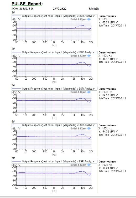 |
|
solderdude
Administrator
measureutternutter
Posts: 4,882
|
Post by solderdude on May 6, 2013 15:15:49 GMT
That's what we need... (the info  ) These are substantially different from WM61A and thus need a different compensation. They cannot be substituted directly in any case if they are used for measurements. Do-able with the filter PCB though. a 5dB lift needs to be compensated (centered around 9kHz) and a 3-4dB dip (centered around 17kHz) needs to be lifted. This is possible by using the 2 filter sections. figure III on John Connovers pages: www.johncon.com/john/wm61a/shows the plot from the WM61A (mind the scales !) It differs from the plot of Panasonic themselves who claim it is flat: www.panasonic.com/industrial/components/pdf/em06_wm61_a_b_dne.pdfnicely flat to 5kHz (as are most electret capsules) |
|


 )
)