solderdude
Administrator
measureutternutter
Posts: 4,881
|
Post by solderdude on Apr 10, 2013 14:03:51 GMT
I am modding a T50RP and took the opportunity to test Dicky's felt. When taking measurements there was a rather BIG difference in LF behaviour between the L and R driver. Very obvious in unmodded condition. The T50RP in question has black drivers and the differences between L and R are much bigger than those of my own. I had experienced the same with 2 of the T40RP-mkII' s I modified earlier and assumed T50's could possibly have closer matched drivers to warrant the difference in price.  Alas it seems to be like being in the lottery. You never know what you are getting. For me, having a measurement rig, this isn't a very big problem as I can quantify all parameters. However, those modding these otherwise lovely headphones MIGHT be facing the same problem without knowing it. Modding it acc to 'standard paths' may therefore lead to different sounding headphones compared to my own efforts. The differences can be amount to 6dB which is quite audible and might be the difference between an excellent headphone and one that sounds nice to very good but not nearly as good as can be had. Having a measurement rig has enabled me to 'tweak' or 'tune' the Right driver to have close to similar response as the Left one. left part are L and R driver below each other with 'standard' modifications (felt in cups, ports closed, wool, baffle loaded, felt on drivers (on both sides)). A rather obvious difference in FR below 2kHz. On the right the results of the results when playing with the port, amount of wool and felt in front of the driver.  Note that the FR plots are of the drivers WITHOUT the correction filter that removes the 3kHz dip and boosts the highs above 10kHz. When the filter is finished I will make plots of the filter+T50RP as well. b.t.w.... The felt used by Dicky has the same sonic properties as the one I use, can't tell 'm apart. Mine is bright white, Dicky's is a bit yellowish which is the only give away. Long haired wool had the same result as my sheep wool in the same quantities by the way. |
|
dicky
quite active
Posts: 230
|
Post by dicky on Apr 10, 2013 17:03:15 GMT
Well, I'm glad the felt is similar - I didn't fancy ripping that out!  The wool is funny stuff - more like hair. I think it is Merino Wool. Would it be possible to check the L/R bass balance using pink noise? |
|
BMF
contributing
Posts: 99 
|
Post by BMF on Apr 10, 2013 17:17:51 GMT
Thanks for the graphs and explanation of your findings. Very interesting. I have done countless individual experiments making one mod change at a time on over 40 sets of T50/40/20RP's and several sets of vintage orthos. I discovered early-on that no matter how precise my methodology and no matter how carefully I measure, cut, and weigh components there are always differences in FR of my modded 'phones. Some sets I've modded were super easy and generated beautiful graphs while others not so much. For example, I'm working on a set of T20RP mk2 for a friend. I have opened this set and tweaked one variable at a time more times than I want to admit and it just won't produce the graphs I've achieved from other sets. They sound really good but the graphs aren't as "pretty." This baffled me for a long time until I came to the same conclusion as you ---> There is variance from one set of headphones in the same line (T50RP's for example) to the next AND variance between the Left and Right drivers of the same set! Consequently, each DIY'er must "Take anyone's mod configuration and make it your own." By this, I mean tuning will likely be required due to differences in: Personal Preferences Hearing Acuity Perception Psychoacoustics Audio Chain ...and....Inherent Driver Variance from the manufacturer. Having a measurement kit and a set of digital scales takes much of the guess work and trial-and-error tuning approach out of the modding:tuning equation. Without these tools, a DIY're must be very patient and very persistent to realize the mod configuration's full potential. I am interested in your comments about the dip at 60 Hz and the bump at 100 Hz. I get almost the same results with Shure Pads and *some* sets of headphones at 40 Hz and 100 Hz. I was able to tune most of this out of most of the sets I've modded, but not all. One more: Do you put felt on the ear side of the drivers to control "hot" treble, or....? What kind, thickness, placement? EDIT: Thanks for the help with loading graphs. After a few false starts, I think I have it sorted out. These graphs are "Raw" with No Smoothing. 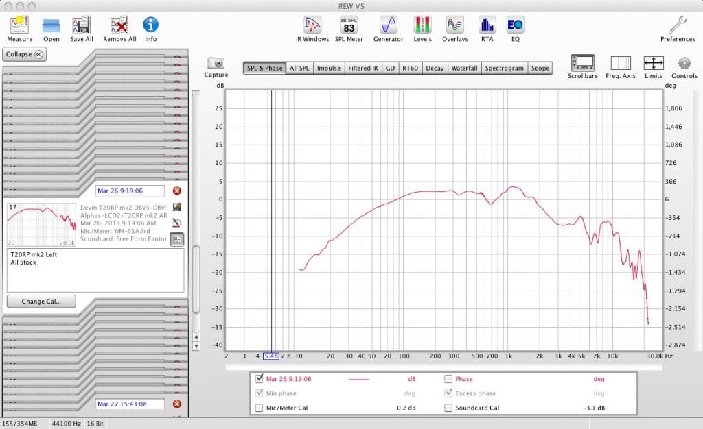 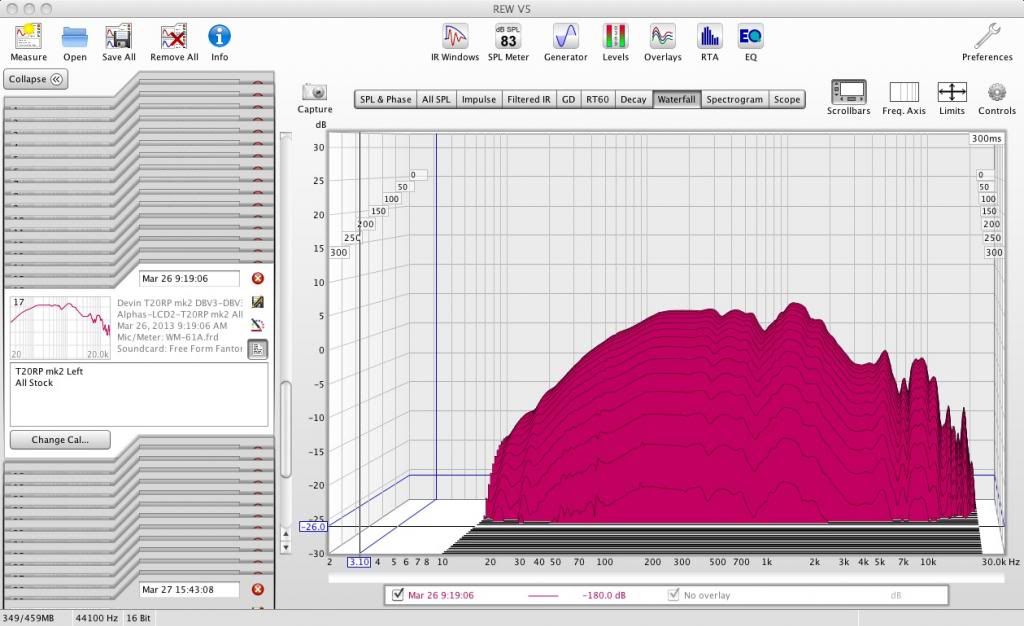 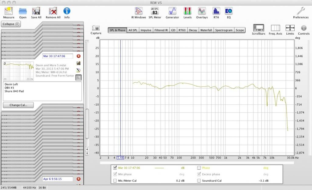 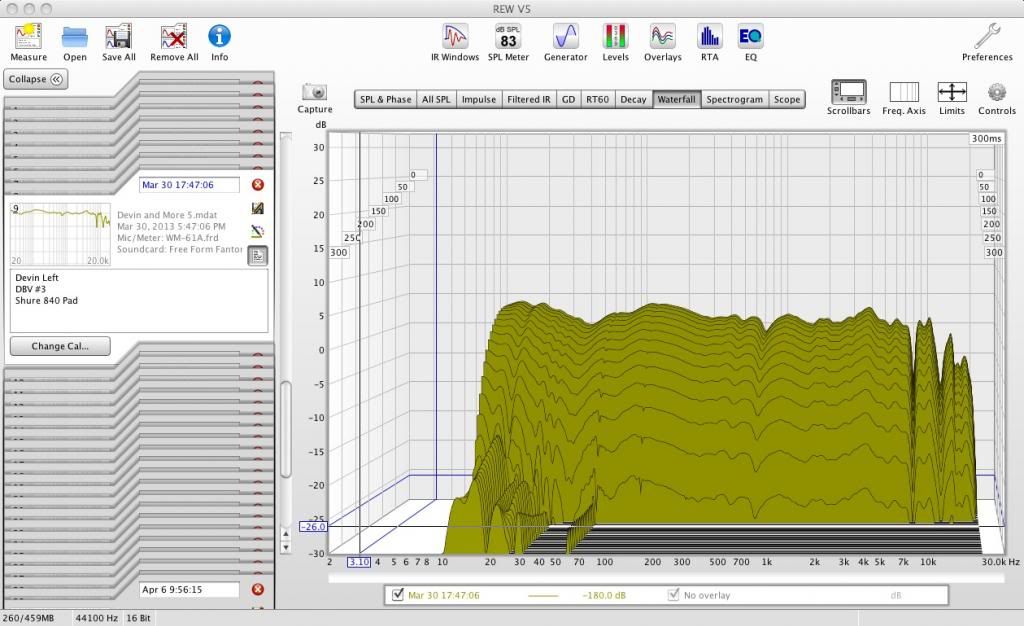 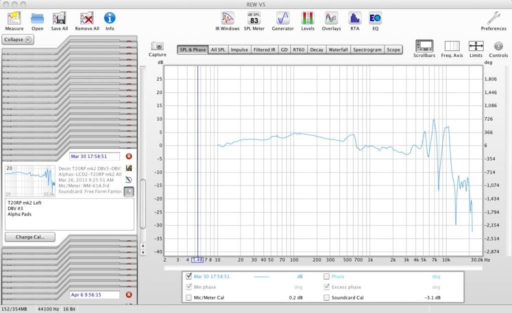 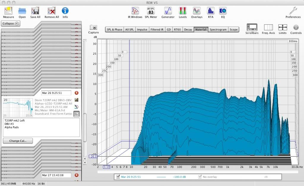 |
|
solderdude
Administrator
measureutternutter
Posts: 4,881
|
Post by solderdude on Apr 10, 2013 20:35:53 GMT
I am interested in your comments about the dip at 60 Hz and the bump at 100 Hz. I get almost the same results with Shure Pads and *some* sets of headphones at 40 Hz and 100 Hz. I was able to tune most of this out of most of the sets I've modded, but not all. One more: Do you put felt on the ear side of the drivers to control "hot" treble, or....? What kind, thickness, placement? Firstly... welcome to this forum. For those that don't know... BMF is responsible for this masterpiece: www.head-fi.org/t/618659/fostex-t50rp-incremental-mods-and-measurementsa MUST read for T50 modders. It was this thread and some Changstar posts that made me curious about the T50. Thanks for that  I think the dip is a resonance. Since this is an ortho it isn't very obvious in the impedance plot but Tyll's measurements show a very slight raise in impedance at that spot. Sometimes resonances appear as dips in the FR instead of the more common peaks. I have looked at Changstar plots and these appear not the have the dip but that's because of the way Purrin measures. Not very detailed/accurate below 100Hz. Too little datapoints that are connected with straight lines. The stock T50's don't have it but drop off fast so seem to be experiencing quite some damping from the stock pads and less damping from the 940 pads. Tyll's plots show the MD has it in a more or less pronounced way. Since it is a resonance you can 'flatten' it by dampening. I have seen that the more you damp the headphone. When you stuff in more wool it is harder for the driver to make larger excursions needed for low frequencies. The dip usually get's smaller and eventually disappears if the roll-off in the highs becomes big enough. If you happen to have drivers that put out a LOT of lows you must damp it more to get it 'flat' and in the process damp the resonances also and thus the dip get's smaller. For this HP one driver already was more damped than the other and thus also showed a smaller dip. I reckon it has something to do with membrane tension. The BIG question is WILL the drivers loosen up over time. I hope not as the FR would change over time and overly damped drivers could and up becoming bassier over time. Hasn't happened to my T40 yet it still measures closely the same and has seen much abuse and hours of music. I use the felt in front and back of the driver. This has to do with the filter correction as well as this boosts the 3kHz and the part above 10kHz. In effect, as the filters have side bands the 8kHz 'peak' that in itself is slightly higher than the average level is raised even more and becomes audible because of it. gives it an unwanted edge. The felt damps everything above 1kHz and lowers that 8kHz peak to less annoying levels. When using the T50 without a filter the felt will probably lower the 8kHz peak too much and may not sound as good. So I use it because of the filter. Without the filter the treble reflector makes sense as the highs are a bit on the lean side in stock form. Do you have experiences with Alpha and Dog pads as well as HiFiman pads ? |
|
BMF
contributing
Posts: 99
|
Post by BMF on Apr 11, 2013 12:48:08 GMT
Thank you for the welcome.
If the -3 dB dip at 40 Hz is a resonance-induced effect, I wonder what's its source? And, what might correct it aside from damping? I've damped all I can on this set of T20RP mk2's and the dip is still present.
I actually like the +3 dB hump at 100 Hz because it adds some weight to vocals without bloating the mids.
I have the components to build your active filter but have not had time to start the project. Do you use the same felt as the sample you sent me? Do you use it With the active filter or also without the filter? If it's primary function is to Reduce the 8 kHz band, I don't need it for most of my sets because I usually see a -6 to -9 "gap" at 8 kHz. I suppose this is also a resonance effect and I've little luck in elevating it to flat without using EQ. Adding in about +6 dB EQ at 8 kHz brings out some "shimmer" but often results in sibilance so there seems to be a fine line to shoot for; maybe +3 dB is the "sweet spot."
I have MD Dog Pads and Alpha Pads. The Dogs are similar to Shure 840 according to Dan and I agree. They add nothing special over Shure 840's, IMO. The Alpha Pads offer amazing comfort, especially with his leather Comfort Strap. The Alpha Pads, however, cause a "saw tooth" FR in the upper register.
I can't seem to upload graphs by using the 'Insert Image" tab. Once I figure out how to do this, I'll post some graphs.
|
|
solderdude
Administrator
measureutternutter
Posts: 4,881
|
Post by solderdude on Apr 11, 2013 13:32:22 GMT
I think dip at around 70Hz is caused by interaction between the air on both sides of the membrane and the membrane itself. Also the pads themselves seem to have something to do with it. All the plots I have seen seem to have this dip in the 70-80 Hz region. Anomalies way below it and above may be due to other aspects perhaps.
Yes the felt I use is the one from the sample.
I only apply it when I am using it with the filter as the filter also lifts a small part of the 8kHz range because of the sidebands of the 3kHz and 22khz dip removers.
Uploading pics is possible by uploading the pics to 'Photobucket' or a similar site and pasting the img codes in the text.
I have not yet seen dips at 8khz, only peaks. Even Luis's and Dan's versions have the 8kHz peak. Also all the DIY efforts and T50 measueremnets from Tyll show the 'peak' at 8kHz. Not present in the Alpha Pads it seems (judging from Changstar) So the wonky FR in that region seems closely related to the used pads.
Actually it is not really a peak but the end of the dip that usually resides between 1k and 8k with the bottom somewhere between 3k and 4k. Above 8kHz the gradual drop-off begins in all the T50's except in a Russian attempt. Don't know how he managed to get highs above 15khz. Perhaps with special pads. I know the DT770 pads don't need the boost above 10khz but they need a steep filter around 8khz.
|
|
BMF
contributing
Posts: 99
|
Post by BMF on Apr 11, 2013 15:28:26 GMT
Don't you mean peaks at 10 kHz?? I get a 10 kHz peak in all my graphs, to some extent, as does Tyll and others.
The Dip I'm referring to in my graphs is at 8 kHz by -6 to -9 dB from one modded set to another.
Curious, as well, I never get a suckout between 3 kHz and 4 kHz. I imagine the greatest amount of the variance is due to the differences in our measurement 'kit', analysis software, and methodology. I use a Panasonic WM-61A mic capsule on an Etymotic triflange tip stuck directly in my ear during measurements + REW analysis software. What do you use?
O.K. do there is no direct upload function. What about the 'Attachment' tab, 4 lines up from >this< 'Message' window?
|
|
solderdude
Administrator
measureutternutter
Posts: 4,881
|
Post by solderdude on Apr 11, 2013 17:16:19 GMT
Indeed the graphs differ most likely of the measurement method. I am quite certain my graphs are pretty accurate as the HD650 which is my only standard reference headphone measures exactly as it should and has no dips in it where it shouldn't. My plots do look a bit extreme but that's because my plots are stretched from top to bottom so to speak compared to other graphs out there. When you take a look at Tyll´s plots www.innerfidelity.com/headphone-data-sheet-downloads scroll to the bottom for the DIY efforts it is easy to spot a dip at 4-5kHz and a peak between 8-10kHz and a drop off below. Tyll's plots are a bit over compensated above 2kHz but in general most of the DIY efforts have a dip in the 4-5kHz region of -10 to -15dB, which is what I measure as well. The reason why some plots show it at 8 and others at 9 or 10 may have something to do with latency of the DAC card and the scan speed or acoustic effects as you have less ´air' trapped between the mic and driver which could alter things as well. I scan really slow (takes 30 seconds) so there is little chance of latency problems. With fast scans (of just a few seconds) the measured frequency can be 'off' a bit. Tyll's plots of the BMG T50 also show a dip at 5kHz of -10dB. Even Luis's expensive Paradox shows a -15dB dip at 5kHz yet when measured by Purrin it shows no dip (well a -5dB lower level only) while Dan's MD shows a -10dB dip at 5kHz and a peak at 10kHz. It is safe to say that the peak shown in my graphs at 8kHz is the same one as yours at 10kHz. Whether this is because of latency or acoustic effects is hard to tell when not held side by side. I also use WM61A and REW as a program. My soundcard is external USB so is why I use a slow scan. Before that I used white noise and Audacity to obtain plots and they match consitently so the frequencies I measure with REW seem accurate. |
|
BMF
contributing
Posts: 99
|
Post by BMF on Apr 11, 2013 18:15:45 GMT
Interesting. Are you posting REW generated plots? What do you mean by "slow scan?" FWIW, the set I sent Tyll was exactly 1 year ago, long before I started to work on DBV #1 through #3.
I'll try loading some shots in Photobucket and transferring them, here. So, do I just click the 'Insert Image" tab at the top, highlight the IMG in the text, and then cut/paste the photo url?
|
|
solderdude
Administrator
measureutternutter
Posts: 4,881
|
Post by solderdude on Apr 11, 2013 20:16:14 GMT
In Photobucket go to the library. Select the picture in the mosaic. On its upper right corner click the 'gear' button. Select 'get links' goto the bottom one; IMG codes. Click on the line... it copies the url.
In the text you are writing simply 'CTRL-V' (paste) the link and the picture will come up when posted.
I have tried to 'remove' the dip (between 1kHz and 8kHz) in several ways but can't get it to go away. Luis seems to have done it but doesn't use Shure pads and think that's the trick. I think it's the pads that cause it. So I solved it electronically as it is easier to duplicate.
I duplicated the DBV as close as possible and wasn't that different from my own version. It only differed in the lows.
It's hard to say what is the correct way to measure. In principle your methodology also includes the ear shape. In mine the 'sound chamber' is round and not filled with the pinnae.
I do have cell rubber on it which doesn't reflect much sound (like the skin) and provides a good seal.
I still plan to make recordings of headphones with a fixed set of music clips and provide the original clip. This way one can easily compare how a headphone 'sounds' and alters the sound from the original file. Works great but have to make some effort.
Very busy on the new filter PCB design at the moment. Coming along nicely.
|
|
BMF
contributing
Posts: 99
|
Post by BMF on Apr 11, 2013 22:13:23 GMT
Thanks for the upload help, SolderDude. I posted graphs in Reply #2, above.
|
|
solderdude
Administrator
measureutternutter
Posts: 4,881
|
Post by solderdude on Apr 12, 2013 21:02:15 GMT
Ah... your dip at 8kHz is actually a peak in disquise. It's flipped over for some reason in your last plot.
In the one on top you can see the 8kHz peak.
the DBV 3 is impressively flat.
Still weird the 3kHz dip isn't there with the 840 pads.
No matter how I mod them it keeps turning up.
It must have something to do with the measurement setup.
Can you lend someone's HD650 and measure that one ?
The HD650 measures quite well.
|
|
BMF
contributing
Posts: 99
|
Post by BMF on Apr 12, 2013 22:25:42 GMT
The order of the graphs is:
1. All Stock T20RP mk2 before modding
2. T20RP mk2 modded to DBV #3 (with Shure 840 Pad)
3. T20RP mk2 modded to DBV #3 with Alpha Pad
I use a Phantom Power Supply I built with WM-61A mic mounted on an Etymotic Triflange Ear Tip (Large) held in place with a ring of hot glue. I stick it in my Left ear as far as it will go and then make my measurements using REW, same method I used for all Incremental Mods and Measurements as well as Pad Rolling Measurements.
You use some sort of Dummy Head, correct? If so, that's one Big source of variance. Do you use a Phantom Power Supply or does your computer/sound card provide Phantom Power to the mic? That may be another.
The 8 kHz Dip I get is an upside down spike?! I don't understand.
|
|
solderdude
Administrator
measureutternutter
Posts: 4,881
|
Post by solderdude on Apr 13, 2013 8:32:19 GMT
Sometimes resonances in the waterfall plot (severe ones) are seen at the bottom of a sharp dip.
To check this simply generate a waterfall plot.
Could also be a cancellation of an 8kHz tone (reflecting of pads edges) like a comb-filter.
I have used one of my filter PCB's and turned it into an optimised (voltage and load impedance) and corrected dedicated mic amp (screened in sealed HF housing) and battery operated for the WM61 where I can dial down the peak it has so calibration is only a matter of levels with a dB meter.
As far as I can tell it measures very flat. Of course I do not have a pinnae on it which changes the amount of air and reflections inside the acoustic chamber that is created.
Ian's T40 has been remeasured by studio guys on their equipment with the filter.
It measures flat there as well so it appears as though the measurements I take are correct.
Also I have my T50 downstairs (also filter corrected) and very accurate speakers. When I have both playing and take off the headphone the sound is very closely the same.
When I correct the HD650 and it is flat is also sounds the same (just not as nicely detailed) as the corrected 50's .
In both cases they measure 'flat" (well the HD650 is MUCH flatter in this case) and have the same sonic signature while playing music.
Israel is copying the rig so I have schematics of the mic frontend and pictures of the rig.
the dummy head are 2 planks opposite each other with mics in the middle and cell foam rubber on the sides.
|
|
BMF
contributing
Posts: 99
|
Post by BMF on Apr 13, 2013 19:26:41 GMT
I added Waterfall Plots in Reply #3, above. Looks like the waterfall has the same dips as the FR graphs. What am I missing?
|
|