solderdude
Administrator
measureutternutter
Posts: 4,881
|
Post by solderdude on Apr 13, 2013 20:21:47 GMT
I added Waterfall Plots in Reply #3, above. Looks like the waterfall has the same dips as the FR graphs. What am I missing? The time scale is not resolving enough to see it. The time scale I can get in REW is 10ms at best (2ms/div) the time scale you used is 30x slower (300ms). In the plots you just see the filters limits used in REW I am planning to do the CSD's in Arta as that can be set to 2ms from rear to back. This is about what is needed to show decay. limit the plots to 100Hz as below that the wavelength becomes too long. The sharp dip with the Alpha pads may just as well be a comb-filter effect or a very sharp area where the pads absorb energy efficiently. Whats a bit suspect is that it is flanked by to peaks and the dip is at the frequency where all T50's seem to peak. I don't have a conclusive answer though. |
|
BMF
contributing
Posts: 99 
|
Post by BMF on Apr 15, 2013 12:26:08 GMT
Thanks for the information, Frans. I haven't been able to get REW to show such short/fast waterfalls using a variety of time x frequency settings. I'll have to dig a little deeper and try other software like ARTA. Is your plank dummy head open or closed all around the mics? Using a Panasonic mic capsule placed in my ear is the method I used for Incremental Mods and Measurements. It's very sensitive to insertion depth, placement angle, type of ear tip used for mounting the mic, headphone clamping pressure, and so forth. There is variance when changing any of these variables so measurements must be made in "comparison groups" during each testing session, if that makes sense. I bought a styrofoam dummy head, drilled an ear canal, and can insert a calibrated SPL probe or Panasonic mic capsule mounted in a silicone tube for measurements. I'm just starting to play with these methods. Here's the SPL meter I use: www.cross-spectrum.com/measurement/calibrated_cm140.htmlSometimes resonances in the waterfall plot (severe ones) are seen at the bottom of a sharp dip. To check this simply generate a waterfall plot. Could also be a cancellation of an 8kHz tone (reflecting of pads edges) like a comb-filter. I have used one of my filter PCB's and turned it into an optimised (voltage and load impedance) and corrected dedicated mic amp (screened in sealed HF housing) and battery operated for the WM61 where I can dial down the peak it has so calibration is only a matter of levels with a dB meter. As far as I can tell it measures very flat. Of course I do not have a pinnae on it which changes the amount of air and reflections inside the acoustic chamber that is created. Ian's T40 has been remeasured by studio guys on their equipment with the filter. It measures flat there as well so it appears as though the measurements I take are correct. Also I have my T50 downstairs (also filter corrected) and very accurate speakers. When I have both playing and take off the headphone the sound is very closely the same. When I correct the HD650 and it is flat is also sounds the same (just not as nicely detailed) as the corrected 50's . In both cases they measure 'flat" (well the HD650 is MUCH flatter in this case) and have the same sonic signature while playing music. Israel is copying the rig so I have schematics of the mic frontend and pictures of the rig. the dummy head are 2 planks opposite each other with mics in the middle and cell foam rubber on the sides. |
|
solderdude
Administrator
measureutternutter
Posts: 4,881
|
Post by solderdude on Apr 15, 2013 18:29:55 GMT
Here is a picture of the rig. The mics are flush mounted and not in a tube that mimics the ear canal. Reasons being. A: I will need to compensate for it and that means a lot of hassle as it isn't a simple straight forward correction curve but a complicated one. No winging it either cause every change of length, diameter and material of the tube will need different compensation. B: I do not plan to measure 'in ears'. When the mics are flush mounted theoretically if one was to measure free field with it (record music or measure speakers) I would have to compensate for LF behaviour. For headphones, however, there is a 'closed' compartment that keeps the sound pressure in a tight area. AFAIK the compensation is not needed (ref measurements with HD650 seem to confirm this). Only the 15kHz peak needs to be addressed, which it is in my filter pre-amp. This way I don't have to compensate with correction curves in test programs. www.johncon.com/john/wm61a/This guy knows about everything there is to know about this cheap mic capsule. a piccy to get the idea... in the middle the screened pre-amp.  |
|
BMF
contributing
Posts: 99
|
Post by BMF on Apr 16, 2013 12:14:52 GMT
Frans, Thanks for the pic. I also used information gleaned from John Conover's web pages about the Panasonic mic capsule. I've tried the IEM artificial ear canal with a mic in one end with little success. I like his "re-flow" technique for easily soldering 26 or 28 gage wire to the tiny solder pads on the WM-61A capsules...works great! Last year, I thought about making a "plank" apparatus with a mic flush mounted in a drilled out hole to simulate the ear canal opening. At that time, I was in the middle of making incremental mods and measurements using my "personal organic Dummy Head" and soon forgot about it as other projects took precedence. Thanks for reminding me. I seem to remember reading about making an artificial pinna for more accurate measurements with the setup you are using. Do you have an opinion about this? By using my own head and ear for mic placement and measurements, I have the benefit of sensory cues necessary for determining consistent headphone placement and clamping force. As you know, these are just two variables that must be controlled for accurate and reliable measurements that cannot be easily duplicated any other way (that I know about). Various sets of T50/40/20RP headphones differ in their clamping force right out of the boxes. Their clamping force tends to diminish as the threads in the external hanger holders wear out from over use. As this occurs, the metal headband hangers are not gripped as firmly resulting in less clamping force and cups that won't stay in place. BTW, this is where super glue or J&B Plasti-Weld is needed to repair the hanger holder threads or shell out $6 Each for new ones. On the other hand, using an apparatus like yours offers the benefit of standardized mic insertion depth and angle in the ear canal opening, important across and within measurement sessions. Do you have comparative measurement graphs for a set of 'phones in their stock form and after modding/tuning them with and without your active filter? Please post them, if you do. Many Thanks, Keith Here is a picture of the rig. The mics are flush mounted and not in a tube that mimics the ear canal. Reasons being. A: I will need to compensate for it and that means a lot of hassle as it isn't a simple straight forward correction curve but a complicated one. No winging it either cause every change of length, diameter and material of the tube will need different compensation. B: I do not plan to measure 'in ears'. When the mics are flush mounted theoretically if one was to measure free field with it (record music or measure speakers) I would have to compensate for LF behaviour. For headphones, however, there is a 'closed' compartment that keeps the sound pressure in a tight area. AFAIK the compensation is not needed (ref measurements with HD650 seem to confirm this). Only the 15kHz peak needs to be addressed, which it is in my filter pre-amp. This way I don't have to compensate with correction curves in test programs. www.johncon.com/john/wm61a/This guy knows about everything there is to know about this cheap mic capsule. a piccy to get the idea... in the middle the screened pre-amp. |
|
solderdude
Administrator
measureutternutter
Posts: 4,881
|
Post by solderdude on Apr 16, 2013 13:28:53 GMT
Plots of Juke's filtered T50 will be posted when I had a chance to make them.
On the first page the unmodded and modded plots are already shown.
When I have finished the filter I will post the plot with the filter.
In my T50 article with and without filter plots are shown on page 4.
I had thought about making something simail shaped and taking up roughly the sama amount of space a pinnae would but it should be easy to mount and take off again if needed.
|
|
BMF
contributing
Posts: 99
|
Post by BMF on Apr 16, 2013 23:27:37 GMT
O.K. Thanks. Do you mount your mic in a silicone tube? Whether yes, or no, what is the diameter of the drilled hole in the planks? Do you mount the mic flush or recessed within the hole? Is the black disk on the planks self-adhesive felt? Keith Plots of Juke's filtered T50 will be posted when I had a chance to make them. On the first page the unmodded and modded plots are already shown. When I have finished the filter I will post the plot with the filter. In my T50 article with and without filter plots are shown on page 4. I had thought about making something simail shaped and taking up roughly the sama amount of space a pinnae would but it should be easy to mount and take off again if needed. |
|
BMF
contributing
Posts: 99
|
Post by BMF on Apr 17, 2013 1:20:50 GMT
Here's a set of T50RP modded that measured flat with the mic in my ear. I am confident they measure flat +/- 3 dB, or better from 10 Hz to 9 kHz by comparing with measurements of an All Stock set of T50RP and my LCD2 v.1 as references. This is what I got when I mounted the mic in my styrofoam Dummy Head. Prepare yourself, it's "not pretty." 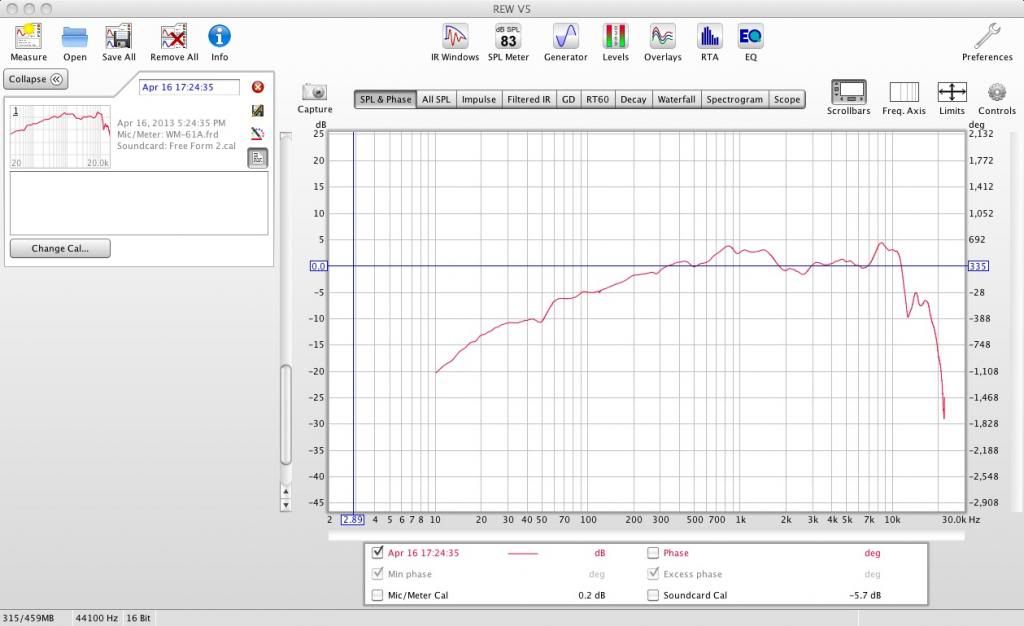 NO Bass or Lower Mids with the Mic in my Styrofoam Dummy Head Here's Dr. Dummy. Be gentle; he's recovering from a Left Parietal Craniotomy and Massive plastic surgery to his left ear: 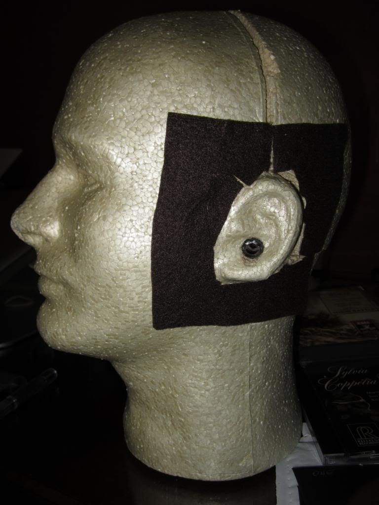 I removed the silicone ear canal and inserted my Etymotic triflange mic from the outside, just as I do with it in my ear. I also tried my calibrated Galaxy C-140 SPL meter and the measurements were even uglier! I will have to spend some time with REW setup this weekend and see what shakes out. I'm in the middle of installing a WM-61A in a John Conover 3mm ear canal made with 2 sizes of silicone tubing as well as a similar setup to Frans' ... |
|
solderdude
Administrator
measureutternutter
Posts: 4,881
|
Post by solderdude on Apr 17, 2013 5:16:05 GMT
I do not use the tubing because you need to compensate for this ( a peak in the 3-5kHz region will appear) and to compensate that you have to have a known reference to quantify it.
I have that now, (HD 650 measurement) but because I do not intend to measure in ears I don't need it and only will bring difficulties.
the planks have a smaller hole in it where the wires go through and a bigger not through-hole where the capsule falls in to.
It is held with a thin layer of foam rubber from the edges, without the foam the mic would fall out.
the black mat is cell foam rubber with an adhesive layer.
The reason why you are missing lows is because of the leakage.
a disadvantage (but real life situation) is the curvature of the head (and the crack in the middle in this case) where there isn't a perfect seal.
That seal is needed and the planks provide that very well.
with the mics in your ear you can hear the seal is good or not, with the head one can only assume/hope it is good and remeasure if needed.
The front of the mic is flush with the cell rubber,
An advantage of the round patches of black rubber is you can easily see if the HP is mounted in the correct position from the side.
In the beginning I even had markings on it but they aren't needed because the black rubber is round and a good indication.
Interesting to compare setups.
I have PCB's available soon, you can even built a proper (and already corrected) front end for the mic(s).
Will make a BOM and tutorial for that in the future.
I am still amazed why you do not get the dip at 3 kHz.
In all cases I had them and had to compensate for it.
|
|
BMF
contributing
Posts: 99
|
Post by BMF on Apr 17, 2013 12:35:52 GMT
<Face:Palm> How could I have missed the obvious?! Expectation Bias, maybe? LOL Thank you for the detailed reply and suggestions. I plan to build a "box" similar to yours, this weekend. It would be interesting and possibly elucidating if you mounted a mic on an Etymotic triflange ear tip and made some measurements with the mic in your ear. This should answer the question about whether or not the mic-mounting method is responsible for the differences we get in the 3 to 4 kHz range. If you want to try it but don't have the tips, I can send you some and/or a mic installed on an ear tip and ready for you to try. BTW, what PCB's are you referring to? Best, Keith I do not use the tubing because you need to compensate for this ( a peak in the 3-5kHz region will appear) and to compensate that you have to have a known reference to quantify it. I have that now, (HD 650 measurement) but because I do not intend to measure in ears I don't need it and only will bring difficulties. the planks have a smaller hole in it where the wires go through and a bigger not through-hole where the capsule falls in to. It is held with a thin layer of foam rubber from the edges, without the foam the mic would fall out. the black mat is cell foam rubber with an adhesive layer. The reason why you are missing lows is because of the leakage. a disadvantage (but real life situation) is the curvature of the head (and the crack in the middle in this case) where there isn't a perfect seal. That seal is needed and the planks provide that very well. with the mics in your ear you can hear the seal is good or not, with the head one can only assume/hope it is good and remeasure if needed. The front of the mic is flush with the cell rubber, An advantage of the round patches of black rubber is you can easily see if the HP is mounted in the correct position from the side. In the beginning I even had markings on it but they aren't needed because the black rubber is round and a good indication. Interesting to compare setups. I have PCB's available soon, you can even built a proper (and already corrected) front end for the mic(s). Will make a BOM and tutorial for that in the future. I am still amazed why you do not get the dip at 3 kHz. In all cases I had them and had to compensate for it. |
|
solderdude
Administrator
measureutternutter
Posts: 4,881
|
Post by solderdude on Apr 17, 2013 14:55:57 GMT
the new filter PCB's that also can make for a nice optimised mic amp for WM61.
I do not have flanges nor spare mics.
I will gladly await your results.
The only differences in that case can be the mic-preamp.
Tried Jukes filter today and one channel worked but the other channel doesn't (the add-on, the filter PCB works on both channels).
Will be looking into that tomorrow...
|
|
juke
very active
Posts: 396
|
Post by juke on Apr 17, 2013 15:44:50 GMT
Tried Jukes filter today and one channel worked but the other channel doesn't (the add-on, the filter PCB works on both channels). Will be looking into that tomorrow... In fairness to Frans he means the add-on I sent him, it sort of looks above as if Frans made a mistake  Syd |
|
BMF
contributing
Posts: 99
|
Post by BMF on Apr 17, 2013 15:48:13 GMT
I use a phantom power supply for the WM-61A with: 2: 2.2 uF caps 2: 10k ohm resistors 2: mini TRS jacks 1: 9-volt battery Mounted on a Radio Shack PCB I am interested in your new PCB and schematic. Still haven't had time to build your active filter but I have all the components in the BOM. the new filter PCB's that also can make for a nice optimised mic amp for WM61. I do not have flanges nor spare mics. I will gladly await your results. The only differences in that case can be the mic-preamp. Tried Jukes filter today and one channel worked but the other channel doesn't (the add-on, the filter PCB works on both channels). Will be looking into that tomorrow... |
|
solderdude
Administrator
measureutternutter
Posts: 4,881
|
Post by solderdude on Apr 20, 2013 14:53:56 GMT
Juke's headphone and filter are finished. Below the results of the objective jury (the measurement rig... not me)  Top left: the L driver (modified) with and without filter. Top right: the R driver (modified) with and without filter. Middle left: CSD left (L channel with filter) Middle left: CSD right (R channel with filter) Bottom left: L and R modified T50RP no filter Bottom right: L and R modified T50RP with filter 'flat' from 10 Hz to 20kHz within +/- 3dB Waterfall plots show no problematic ringing at all You can see on the plots the modded T50RP without a filter isn't even that bad... the filter simply fills in the missing parts. |
|
Rabbit
Administrator
Posts: 7,087
|
Post by Rabbit on Apr 20, 2013 16:56:29 GMT
Frans, the scales are quite different between the FR and WF so they almost look like diffrent headphones. Also, the scale of the FR is quite spread, so those up/downs look quite large in comparison to many other graphs I've seen.
It looks like wuite a dip at 70 and a hump at 25 Hz. Is that the ringing down there? Your WF plots stop at 200 and I'm curious as to whether it gets any stronger down there since it looks like it does from what happens at the bottom of the WF charts,
|
|
solderdude
Administrator
measureutternutter
Posts: 4,881
|
Post by solderdude on Apr 20, 2013 18:40:53 GMT
CSD below 200Hz are rather pointless so are not shown.
This has to do with wavelengths and sample sizes.
The FR plots go down to 10Hz here (mostly I cut them off at 20Hz) both are so low you cannot hear those frequencies anymore b.t.w.
There is some resonance at 70Hz. Most headphones have this, speakers usually have this at a lower frequency because the size/weight ratio is somewhat different.
The CSD's made by REW are not very steep but it does show the important places where ringing occurs and becomes audible (above 1kHz) decays at least 30dB within 1.5ms. The first ms is the limit of the REW program.
I need to install ARTA, they seem to have better algorithms.
Channel balance is within 1dB from 70Hz to 20kHz.
If I had more time to spend on it I might be able to lower the 2dB L-R imbalance to 1dB as well by altering the amount of wool bit by bit till it is as equal as we can get. A slight imbalance that low isn't obvious anyway as the 'positioning' of the soundstage comes from harmonics WAY up higher. the brain is virtually clueless down there. a good example is the subwoofer that is difficult to spot when only listening out for it.
|
|


