solderdude
Administrator
measureutternutter
Posts: 4,881
|
Post by solderdude on Feb 28, 2016 20:26:38 GMT
I HATE it when a tap breaks.
using 3 mm taps is almost an art form if it is to be done perfectly.
So .... there are no holes for the parts in the standard heatsink.
|
|
Crispy
very active
Madrigal music is playing - Voices can faintly be heard, "Please leave this patient undisturbed."
Posts: 776 
|
Post by Crispy on Feb 28, 2016 20:35:39 GMT
I HATE it when a tap breaks. using 3 mm taps is almost an art form if it is to be done perfectly. So .... there are no holes for the parts in the standard heatsink. Know any tricks to get it out easily? This is the first time I have used a tap since school - a very long time ago  The standard heatsink only has holes for the 3 Transistors and 2 holes for case fixing. I will get there in the end - it's just a bump along life's little highway. |
|
Crispy
very active
Madrigal music is playing - Voices can faintly be heard, "Please leave this patient undisturbed."
Posts: 776
|
Post by Crispy on Feb 28, 2016 20:40:56 GMT
using 3 mm taps is almost an art form if it is to be done perfectly. Just re-read your post Frans - how did you know it was a 3mm Tap, u psychic? |
|
solderdude
Administrator
measureutternutter
Posts: 4,881
|
Post by solderdude on Feb 29, 2016 9:54:53 GMT
I don't think it is easy to remove them.
I suggest to drill a hole (2.5mm) next to it and move the transistor sideways IF there is enough space for this.
You can cut the isolating stuff and move that as well for that transistor.
Handtapping M3 isn't easy in aluminium.
start with the 1 ring and turn it in 2 windings, then remove it again and clean the thread go a bit deeper each time.
Then the 2 rings and finally the no-ring.
Of course with a single mnachine tap you could go in all the way at once in a low speed.
Important to not bend the tools, not even the slightest.
That is hard to do with a handtool.
|
|
Crispy
very active
Madrigal music is playing - Voices can faintly be heard, "Please leave this patient undisturbed."
Posts: 776
|
Post by Crispy on Feb 29, 2016 20:51:36 GMT
I don't think it is easy to remove them. I suggest to drill a hole (2.5mm) next to it and move the transistor sideways IF there is enough space for this. You can cut the isolating stuff and move that as well for that transistor. Handtapping M3 isn't easy in aluminium. start with the 1 ring and turn it in 2 windings, then remove it again and clean the thread go a bit deeper each time. Then the 2 rings and finally the no-ring. Of course with a single mnachine tap you could go in all the way at once in a low speed. Important to not bend the tools, not even the slightest. That is hard to do with a handtool. Thanks Frans, I will keep that in the back of my head and see if it is viable or not, I will know better once the new carbide drill bit arrives. While I was at it I googled about taps and found out that taps from a set are usually CRAP and easily break. Mine was from a set and only contained one 3mm tap? So I also ordered some higher quality HSS taps from UK Drills containing Taper, Plug & Bottoming hand taps. So when i get around to doing my other amp I hopefully will not have the same problem? |
|
solderdude
Administrator
measureutternutter
Posts: 4,881
|
Post by solderdude on Mar 1, 2016 9:32:59 GMT
There are 3 tap sets (which have 3 different taps increasing in diameter) and there is a machine tap. The latter has a different shape and needs to be driven in the (2.5mm) hole in one go. Machine taps look like this:  Usually all silver metal color though. typical tap set: 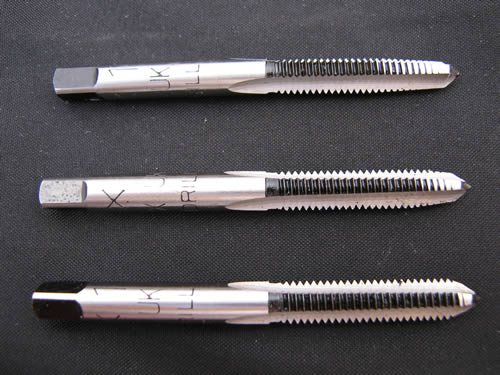 |
|
Crispy
very active
Madrigal music is playing - Voices can faintly be heard, "Please leave this patient undisturbed."
Posts: 776
|
Post by Crispy on Mar 1, 2016 9:51:45 GMT
There are 3 tap sets (which have 3 different taps increasing in diameter) and there is a machine tap. The latter has a different shape and needs to be driven in the (2.5mm) hole in one go. Machine taps look like this: Usually all silver metal color though. typical tap set: It looks like the one I broke was a machine tap because there was only one in the set and was not tapered. The typical set you have shown is like the new set I ordered - gradually increasing in diameter. Fingers crossed I will not have any problems with these? |
|
Crispy
very active
Madrigal music is playing - Voices can faintly be heard, "Please leave this patient undisturbed."
Posts: 776
|
Post by Crispy on Mar 7, 2016 20:21:31 GMT
It's back to square one again Frans  The first turn of the new 2.5mm carbide drill and it broke straight away. I then thought drill next to the broken tap like you suggested and did not have a problem drilling the hole, the problem came to tapping it out. I was using the first tap (tapered) and was almost at the bottom when that also snapped (so much for getting new ones) So I thought no problem just drill a 4mm hole on the other side and glue a 3mm bolt into that. So far so good. with a little jiggery pokery I managed to get the new tranistors in place:  You will see from the pic above the 2nd transistor from the left (bolted one) was almost touching the third transistor, so I put some heat shink material inbetween so that it did not touch. Fixed it all back together and switched it on - and to my suprise no big bang  So I thought get it back in the system - Sat night when my wife was on a night out I put it back in place and fired it up, it played music for about a minute of the first track and then it blew up.  Today I stripped it back down to asses the damage, I found the bolt that I had glued in had come out and the transistor was off the heatsink - no wonder it blew. other damage was to some resistors: Below R15 totally blown.  I also don't like the look of R45 & R46 these are right next to the 2nd transistor above.  I worked out the value of R45&46 as being 0.22ohms 5% but do not have a clue what wattage rating they may be - do you think 3 or 5W? So after my little adventure I think I will forget about the extra trasistors and try to get my amp up and running again as it was, too much hassle with drilling and tapping the heatsinks and I definitely don't want to have the same problems with my other amp. Thanks for your time and patience Frans |
|
solderdude
Administrator
measureutternutter
Posts: 4,881
|
Post by solderdude on Mar 7, 2016 22:39:23 GMT
The power resistors are about 3W
If you are going to leave out the transistor anyway there is no need to replace those resistors, you can just leave them in there.
R15 is a bigger problem.
Possibly the transistors connected to it are fried as well.
|
|
Crispy
very active
Madrigal music is playing - Voices can faintly be heard, "Please leave this patient undisturbed."
Posts: 776
|
Post by Crispy on Mar 8, 2016 20:35:06 GMT
The power resistors are about 3W If you are going to leave out the transistor anyway there is no need to replace those resistors, you can just leave them in there. R15 is a bigger problem. Possibly the transistors connected to it are fried as well. Thanks Frans, I thought there may be more damage? I will get the board stripped down again when I get time and we will take it from there, fingers crossed I may get away lightly.  |
|
Crispy
very active
Madrigal music is playing - Voices can faintly be heard, "Please leave this patient undisturbed."
Posts: 776
|
Post by Crispy on Apr 11, 2016 14:31:55 GMT
The power resistors are about 3W If you are going to leave out the transistor anyway there is no need to replace those resistors, you can just leave them in there. R15 is a bigger problem. Possibly the transistors connected to it are fried as well. I found a bit of spare time today Frans and measured the A92 & A42 transistors as follows:  The measurements don't mean much to me? can you tell me if any have blown and which are the best ones to keep in place? the reason being is I can only order packs of 5 and there are 6 PNP and 6 NPN, so my plan is to replace all but the best out of each. OH I nearly forgot - would these be volts DC? Thanks again Chris |
|
solderdude
Administrator
measureutternutter
Posts: 4,881
|
Post by solderdude on Apr 11, 2016 21:35:45 GMT
possibly dodgy:
T2, T4, T5, T7, T8, T10, T12.
To get correct measurements the transisitors would need to be removed from the board and then measured.
If unsure you could send the PCB to me as well and I can have a look at it.
|
|
Crispy
very active
Madrigal music is playing - Voices can faintly be heard, "Please leave this patient undisturbed."
Posts: 776
|
Post by Crispy on Apr 13, 2016 7:27:17 GMT
possibly dodgy: T2, T4, T5, T7, T8, T10, T12. To get correct measurements the transistors would need to be removed from the board and then measured. Thanks Frans, I will remove them all and re-measure them and let you know  If unsure you could send the PCB to me as well and I can have a look at it. That's very kind of you - I will see how I get on and if I run into trouble I will ship it out to you. The output transistors were a right pig to get out even using your method of flooding all three joints with solder and pulling them out, so I decided to just cut them out and replace them. Some of the tracks lifted and one actually broke as you can see from the pic below. So I stuck the tracks back down with a strong contact adhesive and scraped all the tracks back and soldered the tracks to strengthen them - don't know if this was a good idea or not, but they seemed useless flapping about   |
|
Crispy
very active
Madrigal music is playing - Voices can faintly be heard, "Please leave this patient undisturbed."
Posts: 776
|
Post by Crispy on Apr 13, 2016 20:03:50 GMT
|
|
solderdude
Administrator
measureutternutter
Posts: 4,881
|
Post by solderdude on Apr 13, 2016 21:19:45 GMT
those are the correct transistors.
As the amp works on +/- 80V (160V) a 200V rating would already have been enough.
So 300V is more than O.K.
PNP is rated for -300V and NPN for +300V
Transistors are always spec'd for DC ratings but mostly just voltages are given.
|
|


