|
|
Post by ronzo56 on Nov 26, 2017 13:10:49 GMT
I may give it a try. That high voltage concerns me. Yeah my bad luck was leaving the house and not telling everyone to leave the stereo alone. Did a little research. Apparently the transformers on the newer models have a reputation for failing. Just strange that all three speakers went bad right after they were messed with. Our utility here is not known for power surges at least not big enough to fry electronics. I have never heard of it happening. It's publicly owned and they really are well run. I love the Quads, but they are fussy creatures. On the other hand, I would never have the Dunlavy SC-IV/A's if this diaster hadn't happened. And I love their sound. Great imaging. Might give a go at the sub woofer first. It a least makes some sound.  |
|
solderdude
Administrator
measureutternutter
Posts: 4,887
|
Post by solderdude on Nov 26, 2017 14:45:05 GMT
The 3 speakers also are all stand-alone.
ESL63 speaker terminals and the high voltage are completely separated.
The power transformer inside has 2 secondary windings.
One for a low voltage powering the spark protection circuit and a separated winding for high voltage.
It's the latter winding that creates problems over time.
Most likely it is just a matter of replacing that transformer.
The 2 audio transformers will probably be O.K.
|
|
|
|
Post by ronzo56 on Nov 26, 2017 15:24:32 GMT
Thanks Frans. I have a friend that is a computer hardware engineer. I might have him take a look under the hood. Hopefully they still make the transformers.
|
|
solderdude
Administrator
measureutternutter
Posts: 4,887
|
Post by solderdude on Nov 26, 2017 16:05:39 GMT
The HV winding is 600V AC.
The lower voltage winding around 9V AC (assumption, I won't be far off)
You can always use separate transformers that provide the 9V AC (100mA is enough) and other transformer(s) to create the 600V AC.
|
|
|
|
Post by ronzo56 on Nov 26, 2017 17:05:02 GMT
Thanks Frans for the info. I'll talk to my friend and see if he's into some repair work.
|
|
Crispy
very active
Madrigal music is playing - Voices can faintly be heard, "Please leave this patient undisturbed."
Posts: 779 
|
Post by Crispy on Nov 30, 2017 16:50:01 GMT
The Parts arrived yesterday and I quickly soldered them in place, thinking this will be OK it will work  I pluged the power into the board and guess what - yes BANG. The fuse in the plug blew, the fuses in the board are OK so is the new themistor  On reflection should I have put the board back into the TV before plugging in the mains? thinking more about grounding? I heard and saw where the bang came from and narrowed it down to a power mosfet. I also had a closer look at the solder joints and could see rings around the joints (not good), so I am guessing this was the root of all the problems to begin with? 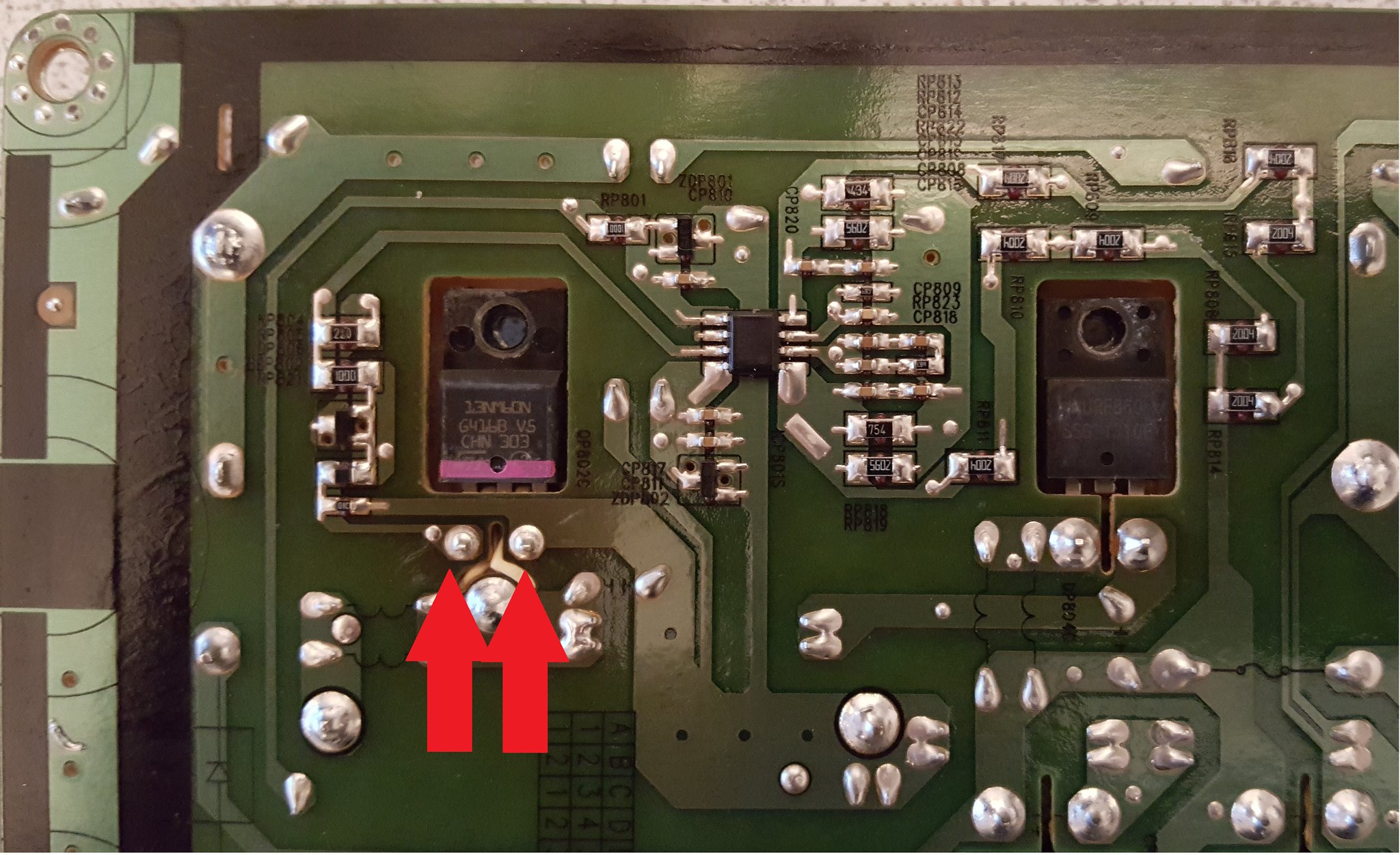 Frans, have you got any suggestions how I can get the heatsink off the board to replace the mosfet? it looks almost impossible. 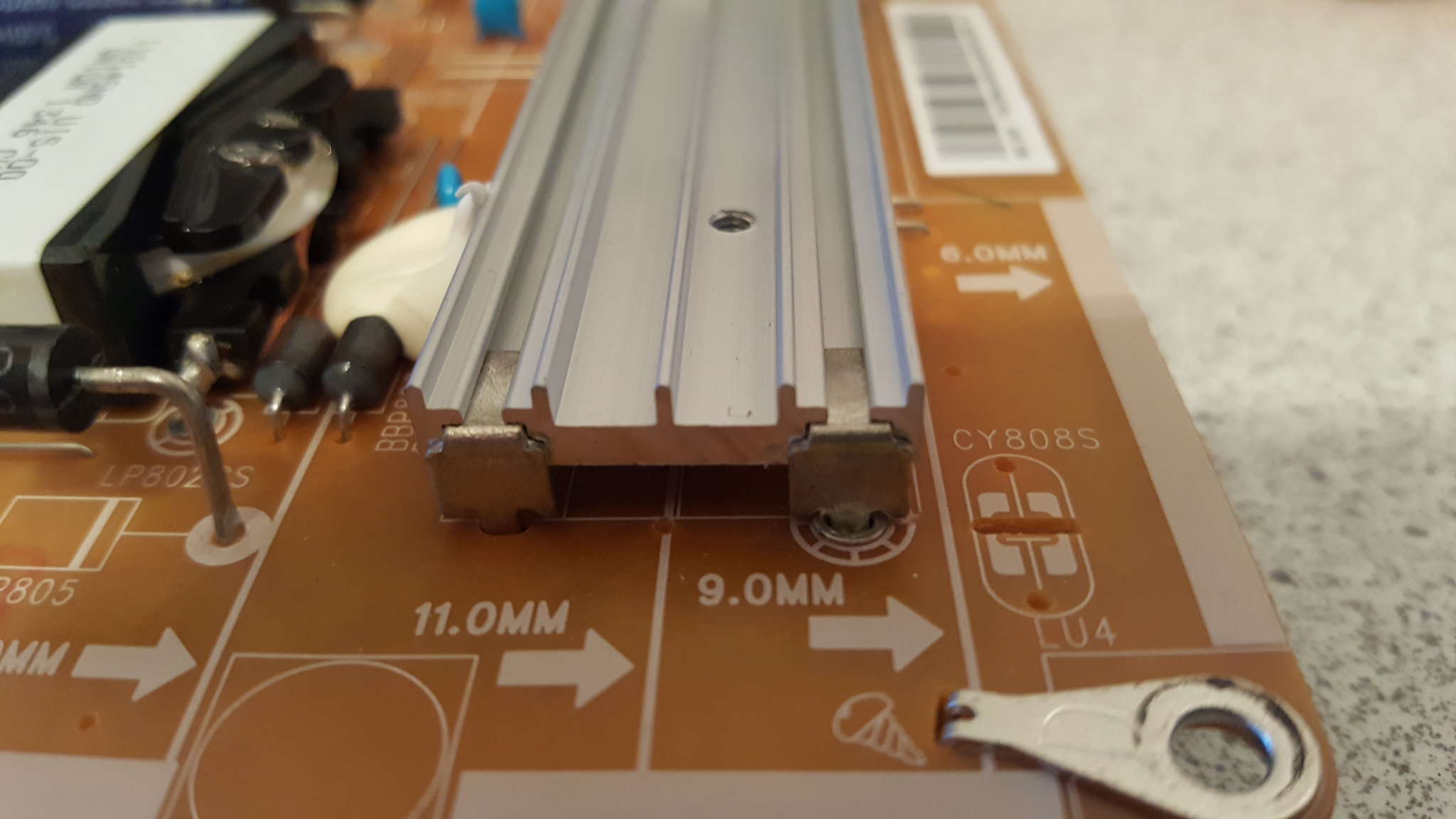 Is there anything else that may need checking as this will be probably my last attempt to repair it? Thanks Chris |
|
solderdude
Administrator
measureutternutter
Posts: 4,887
|
Post by solderdude on Nov 30, 2017 19:08:59 GMT
The MOSFET does seem to have 'solderrot' on 2 pins. The dark 'ring' in the solder.
You could try to replace that one.
To remove the heatsink you need a solderiron with at least 50W.
Heat the pin you want to remove and use a screwdriver between the PCB and heatsink to force it upwards.
Go around the 4 solder lugs each time lifting them a little.
No guarantees that will be the last thing that needs to be done.
Also check the rectifier again.
It can only take so much obuse.
I recommend to fully re-fit the PCB and connect everything before trying again.
|
|
|
|
Post by Mr Trev on Nov 30, 2017 23:09:04 GMT
The Parts arrived yesterday and I quickly soldered them in place, thinking this will be OK it will work  I pluged the power into the board and guess what - yes BANG. The fuse in the plug blew, the fuses in the board are OK so is the new themistor  On reflection should I have put the board back into the TV before plugging in the mains? thinking more about grounding? I heard and saw where the bang came from and narrowed it down to a power mosfet. I also had a closer look at the solder joints and could see rings around the joints (not good), so I am guessing this was the root of all the problems to begin with? Frans, have you got any suggestions how I can get the heatsink off the board to replace the mosfet? it looks almost impossible. Is there anything else that may need checking as this will be probably my last attempt to repair it? Thanks Chris Wow. I admire your devotion to the TV. I would have stomped on the LCD panel and hung it on the wall as "modern art" long ago Last time I tried to fix a TV was one of those old CRT things. It bit me a few times |
|
Crispy
very active
Madrigal music is playing - Voices can faintly be heard, "Please leave this patient undisturbed."
Posts: 779 
|
Post by Crispy on Dec 1, 2017 17:21:21 GMT
Wow. I admire your devotion to the TV. I would have stomped on the LCD panel and hung it on the wall as "modern art" long ago Last time I tried to fix a TV was one of those old CRT things. It bit me a few times No devotion at all, I am just a tight arsed Yorkshireman who hates waste  having said that - the big Irish srewdriver (Hammer) has nearly come out a few times. One last repair attempt and then I will buy a replacement fully working PSU and fix it that way - cheaper than a new TV. They don't ake things to last nowadays - its only about 18months old? My old Panasonic plasma TV never ever blinked once in about ten years. |
|
Crispy
very active
Madrigal music is playing - Voices can faintly be heard, "Please leave this patient undisturbed."
Posts: 779 
|
Post by Crispy on Dec 1, 2017 17:35:07 GMT
The MOSFET does seem to have 'solderrot' on 2 pins. The dark 'ring' in the solder. You could try to replace that one. To remove the heatsink you need a solderiron with at least 50W. Heat the pin you want to remove and use a screwdriver between the PCB and heatsink to force it upwards. Go around the 4 solder lugs each time lifting them a little. No guarantees that will be the last thing that needs to be done. Also check the rectifier again. It can only take so much obuse. I recommend to fully re-fit the PCB and connect everything before trying again. Thanks Frans, I managed to get the heatsink off with the method you suggested, tested the mosfet and yeh its blown. I noticed on this particular heatsink there was no heat transfer paste on the two components which again may not have helped. You were right the rectifier seems shot also? New readings: 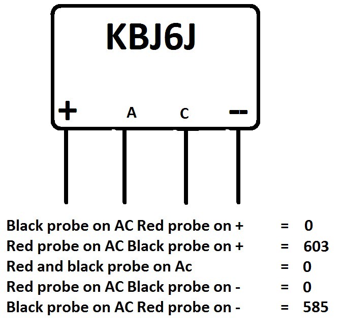 After watching a youtube video it said about checking the SMD diodes under the board - didnt even know they had any? I checked and majority were fine except these three. I think they are diodes? the markings say PJ3166 and underneath that SK24. I cannot find any information at all about these components - pic below: 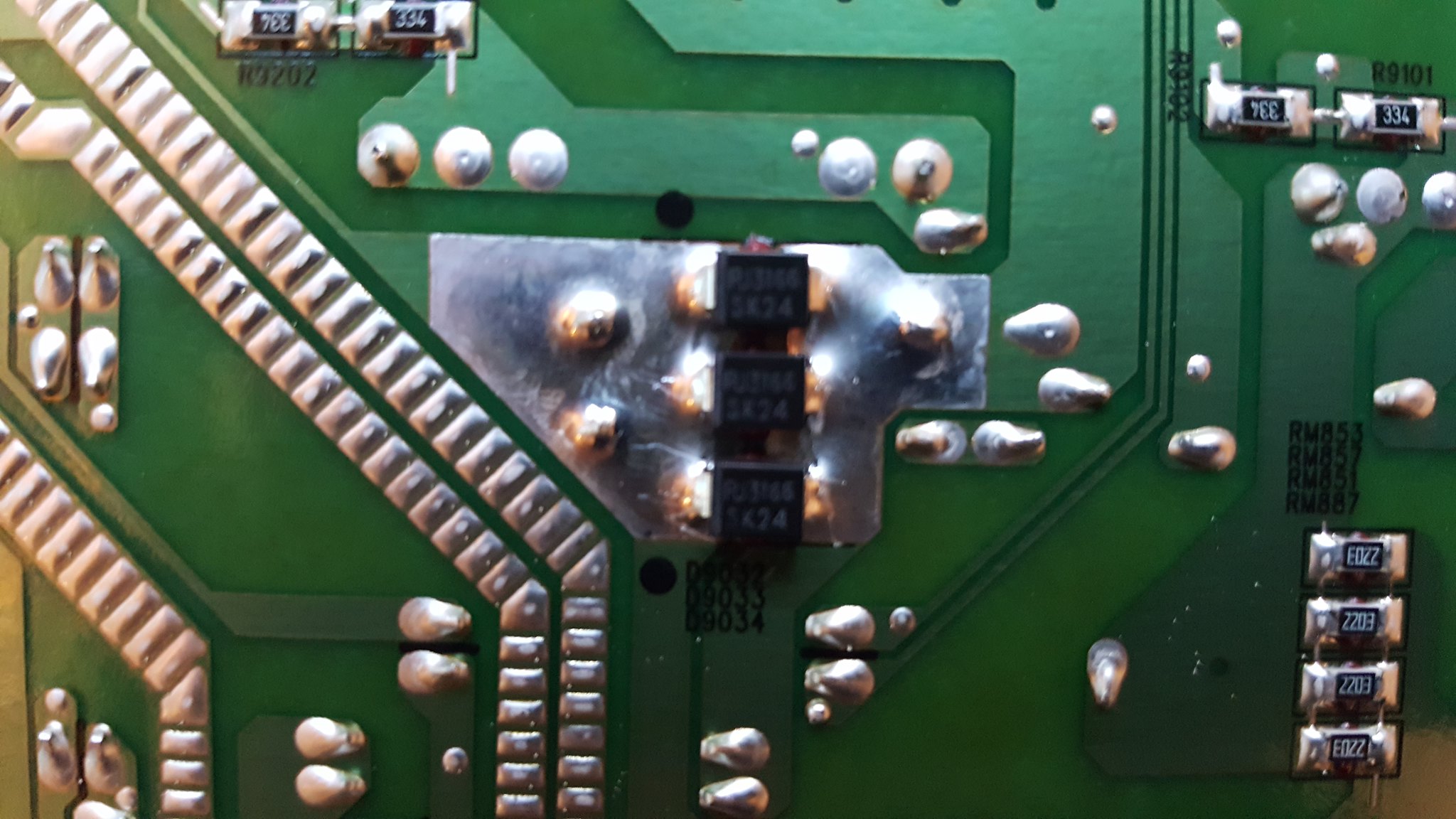 It also seems strange to put 3 diodes alongside of each other and then connect them up as one? Position of the diodes on the full board. 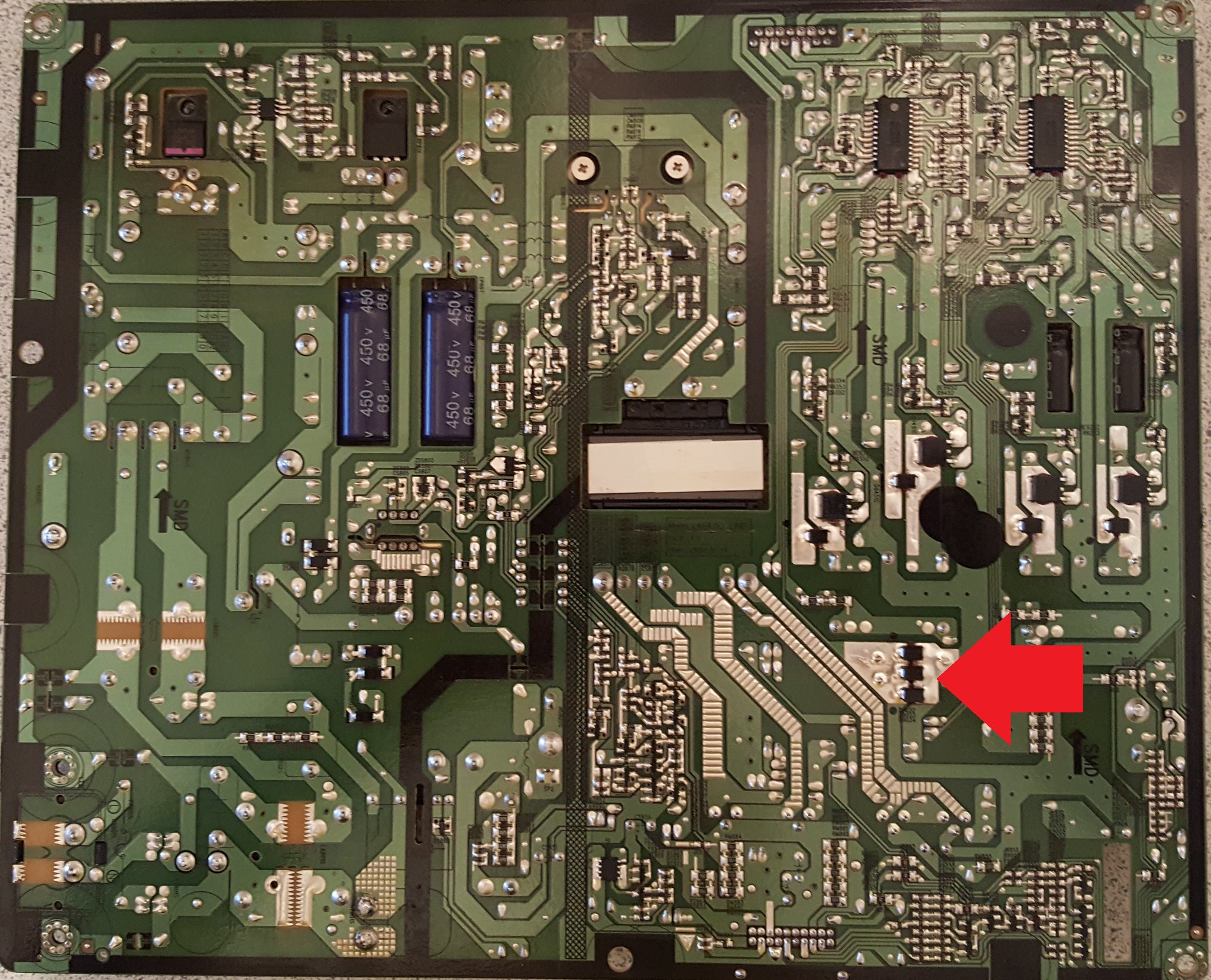 Any help appreciated Chris |
|
solderdude
Administrator
measureutternutter
Posts: 4,887
|
Post by solderdude on Dec 1, 2017 19:45:51 GMT
Yes, the rectifier is gone. Might be due to a defective MOSFET. Now that the NTC is working fine again a high current will have blown it up. The trouble now is that no one knows what other parts also may be fried. Those diodes may have to be unsoldered to check them: pdf.datasheetcatalog.com/datasheet/dccomponents/SK26.pdfAnd then the question is why they gave up and what they took along. |
|
Crispy
very active
Madrigal music is playing - Voices can faintly be heard, "Please leave this patient undisturbed."
Posts: 779 
|
Post by Crispy on Dec 3, 2017 20:31:45 GMT
Thanks for the link  You amaze me again Frans, when in circuit on diode test mode they just beep no matter which way around you test them. Unsoldered they all measure approx 185 in one direction and 0 in the other direction, so I guess they have not blown? |
|
|
|
Post by drumdrym on Dec 4, 2017 0:04:43 GMT
The TRIALS and TRIBULATIONS of a Yorkshireman,
guess the worst part will be "YGLW",
but hey stick in there Chris it's all good reading,
and worth the effort for the satisfaction when it all comes right.
|
|
Crispy
very active
Madrigal music is playing - Voices can faintly be heard, "Please leave this patient undisturbed."
Posts: 779 
|
Post by Crispy on Dec 6, 2017 17:16:50 GMT
The TRIALS and TRIBULATIONS of a Yorkshireman, guess the worst part will be "YGLW", but hey stick in there Chris it's all good reading, and worth the effort for the satisfaction when it all comes right.  Its no fun when everything works just as should Alan, somebody up there has it in for me  Anyway the good news is the bridge rectifier came today and I soldered it in place, I took a reading again and it measured the same as the one that I had just taken out so I thought something along the line must have blown. I then plucked up the courage to put the board back in the tv and fingers crossed plugged it in. BANG - ha ha only joking  To my amazement just a soft click like the TV was switching on and low and behold the standby light was on. Took it back downstairs and plugged it into the aerial and bingo TV back to normal. The total cost of my little adventure was £8.76  So tonight I will be able to watch peaky blinders on the big screen again. Thank you for all your help Frans its appreciated. Pic of TV now working again: 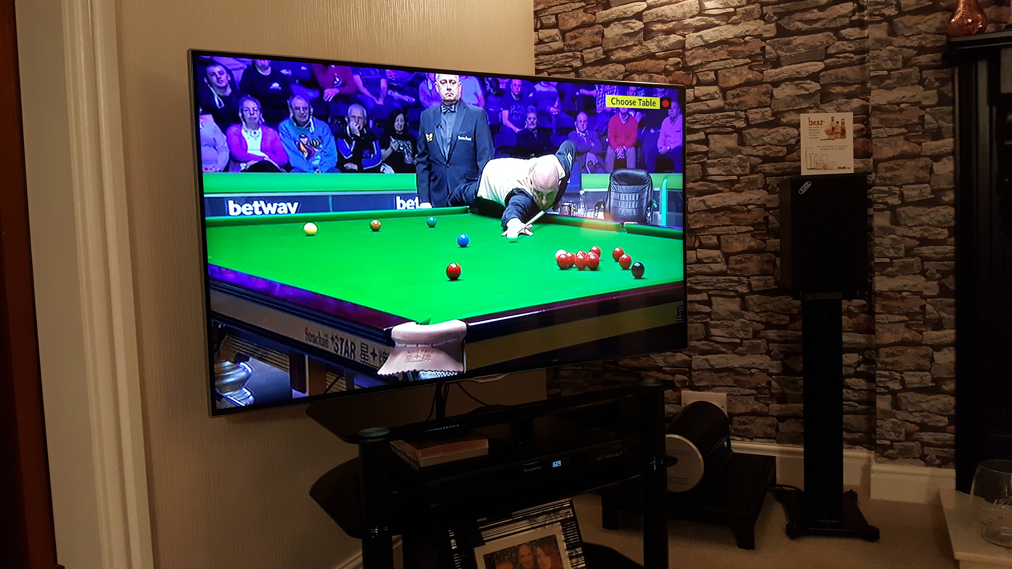 So if you are reading this Ron, there is hope for your ESL speakers  |
|
solderdude
Administrator
measureutternutter
Posts: 4,887
|
Post by solderdude on Dec 6, 2017 18:51:23 GMT
GREAT !
A lot cheaper than buying a new one.
Samsung would probably have replaced the power PCB and charged you anywhere between 200 and 300 GBP most likely.
|
|