Crispy
very active
Madrigal music is playing - Voices can faintly be heard, "Please leave this patient undisturbed."
Posts: 779 
|
Post by Crispy on Jul 26, 2015 18:59:49 GMT
Frans, I may have bitten off more than I can chew with my latest project? but I like a challenge  I bought a pair of faulty Dutch Final 03 Electrostatic hybrid speakers off E-Bay for £250. The information about these speakers on the internet is just about 0 and I could only really find a bit about them on this forum: www.diyaudio.com/forums/planars-exotics/46477-final-0-3-hybrid-esl.htmlEver since hearing some Quad Electrostatic speakers many moons ago I have always wanted to own some electrostatics, but they have always been out of my price range and also the normal footprint is too large for my living room. The Final 03 footprint is almost identical to my Acoustic Energy AE1 loudspeakers except they are slightly taller. They are in need of some much loved TLC which I intend to do - slowly but surely as I can keep listening to my AE1's whist repairing the Finals. Have you got any tips on how to work on these speakers with very high DC voltages without killing myself. Here are some pics: 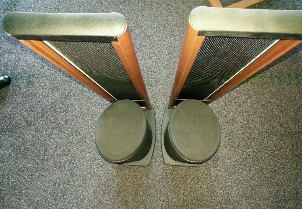 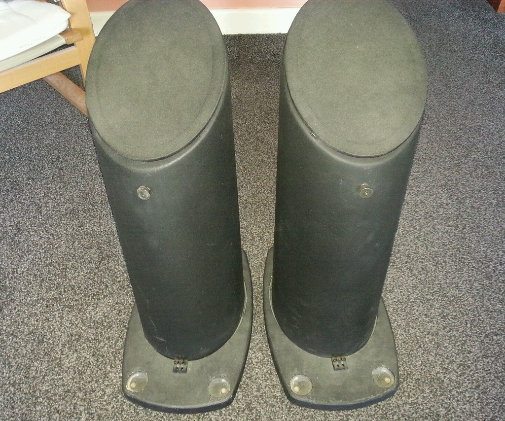 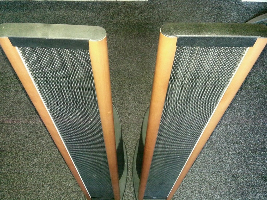 As you can see they have been well neglected.  The person I bought them from said the left speaker was not working and the input transformer needed to be replaced. He sent me some schematics - but they are not true to the board and seem to be from some Newton Sound System speakers. I have re-produced the schematic as best that I can to be true to the board: Pic below. 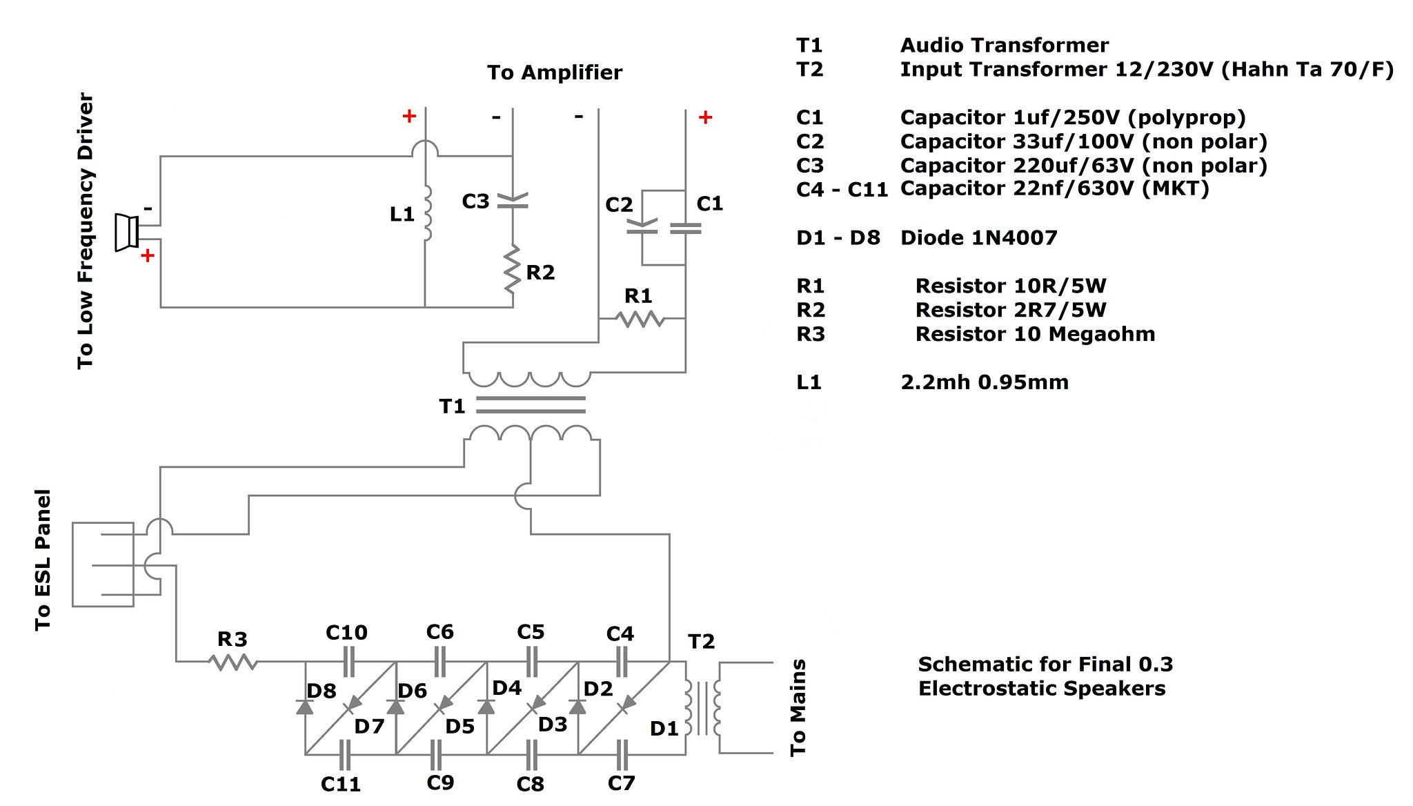 The schematic he sent me. 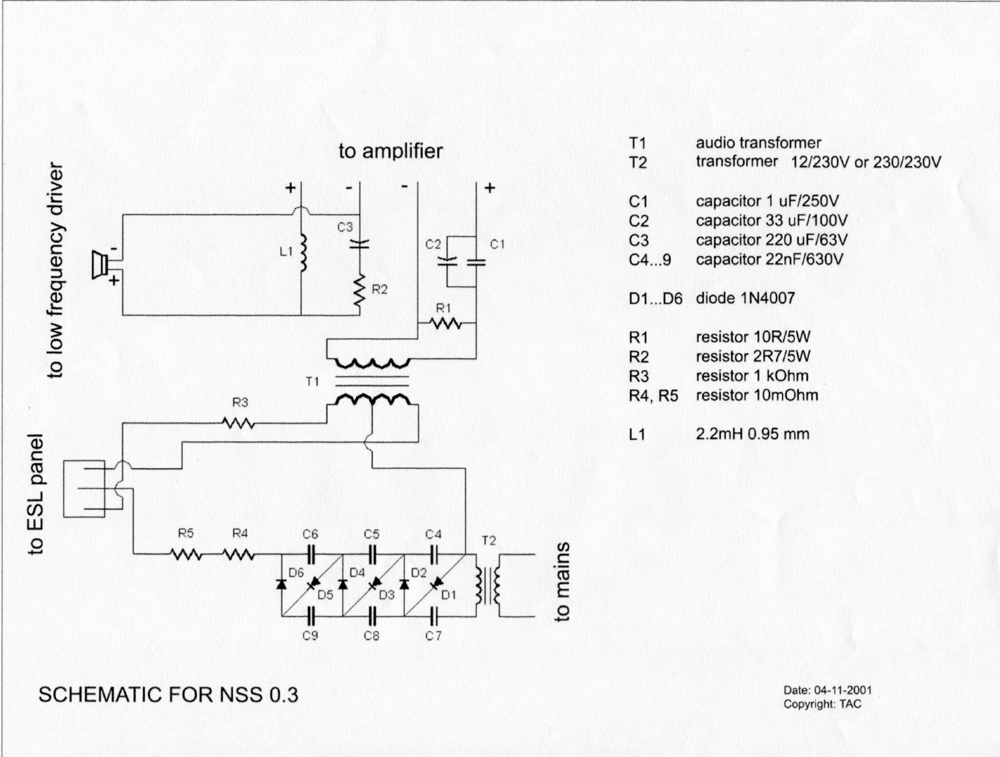 The board in the speaker 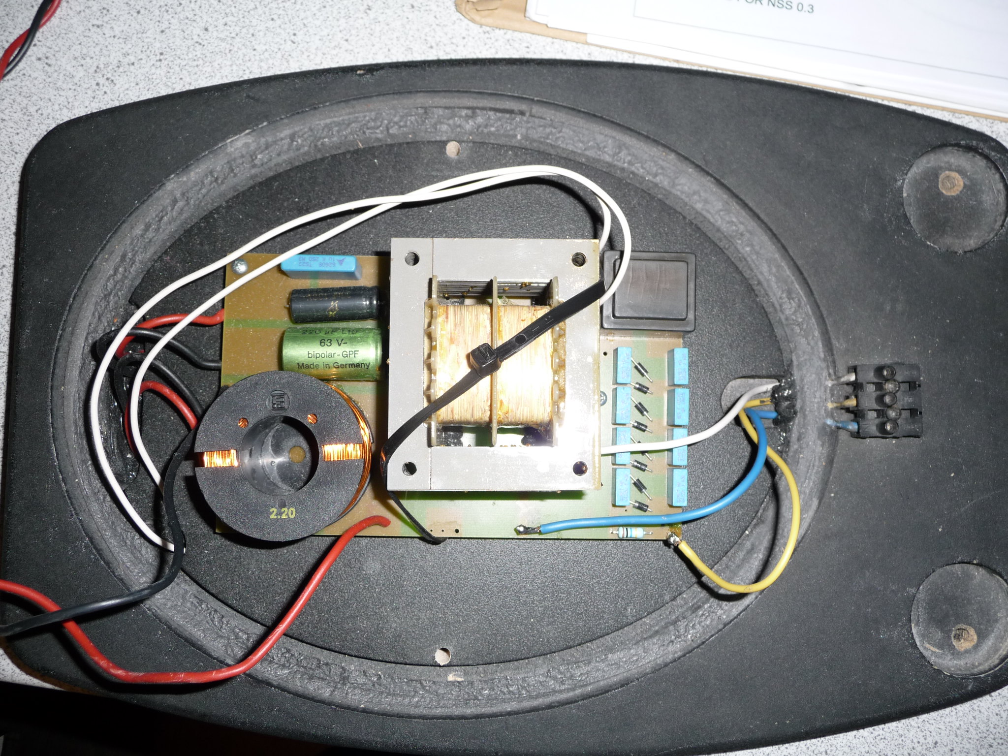 So the first question Frans, is what do you think to the components etc and is there anything you would change? or would I be better making completely new boards? |
|
solderdude
Administrator
measureutternutter
Posts: 4,887
|
Post by solderdude on Jul 26, 2015 19:46:10 GMT
You should first check the transformers.
I suspect, however, that this is the picture of the defective side.
FWICS the mains transformer (the small black one top right corner) looks burnt.
Take out the PCB and measure Ohms on the primary and secondary side of the small transformer.
Check if the other one looks 'normal'.
Finals are excellent speakers.
Just NEVER work on them with audio playing and wait for some time after the mains is disconnected.
Preferably short the blue and yellow wire before working on the electrostat (don't forget to remove the short when testing/using !!)
|
|
Crispy
very active
Madrigal music is playing - Voices can faintly be heard, "Please leave this patient undisturbed."
Posts: 779 
|
Post by Crispy on Jul 27, 2015 17:14:01 GMT
You should first check the transformers. I suspect, however, that this is the picture of the defective side. FWICS the mains transformer (the small black one top right corner) looks burnt. Take out the PCB and measure Ohms on the primary and secondary side of the small transformer. Check if the other one looks 'normal'. Finals are excellent speakers. Just NEVER work on them with audio playing and wait for some time after the mains is disconnected. Preferably short the blue and yellow wire before working on the electrostat (don't forget to remove the short when testing/using !!) Thanks Frans, it's good to know that they are excellent speakers once mended and restored.  I have checked both input transformers and the Left Amp reads zero volts AC and the Right Amp reads 330 volts AC at their output. Which corresponds to what the guy said who sold me them. Both the input 12V AC/AC psu measure 15.3VAC & 15.8VAC - I presume these are higher because there is no load on them? Both input transformers look brown and discoloured and so does both the underneath of the boards. see pics: Left amp transformer 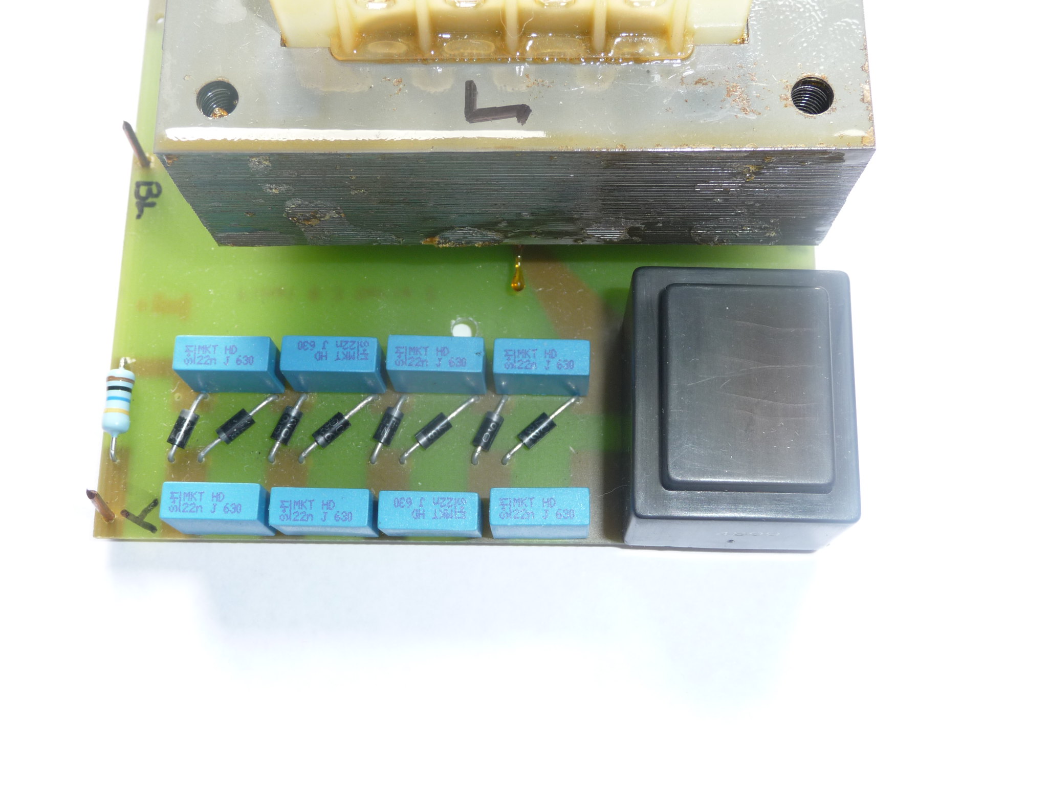 Right amp transformer 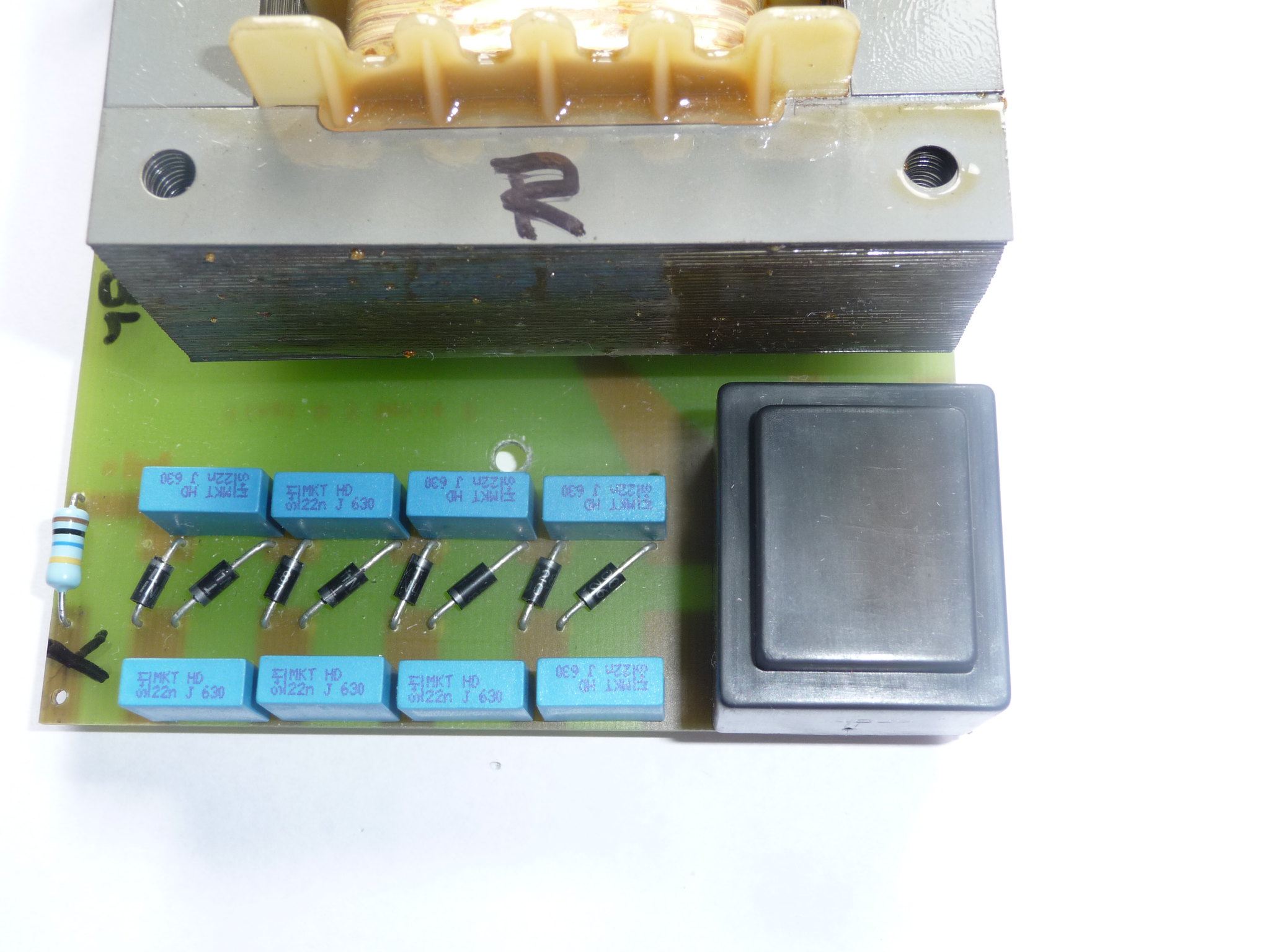 left amp underboard 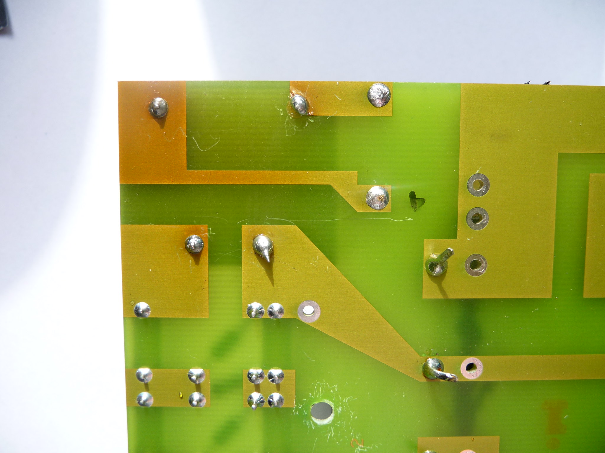 Right amp underboard 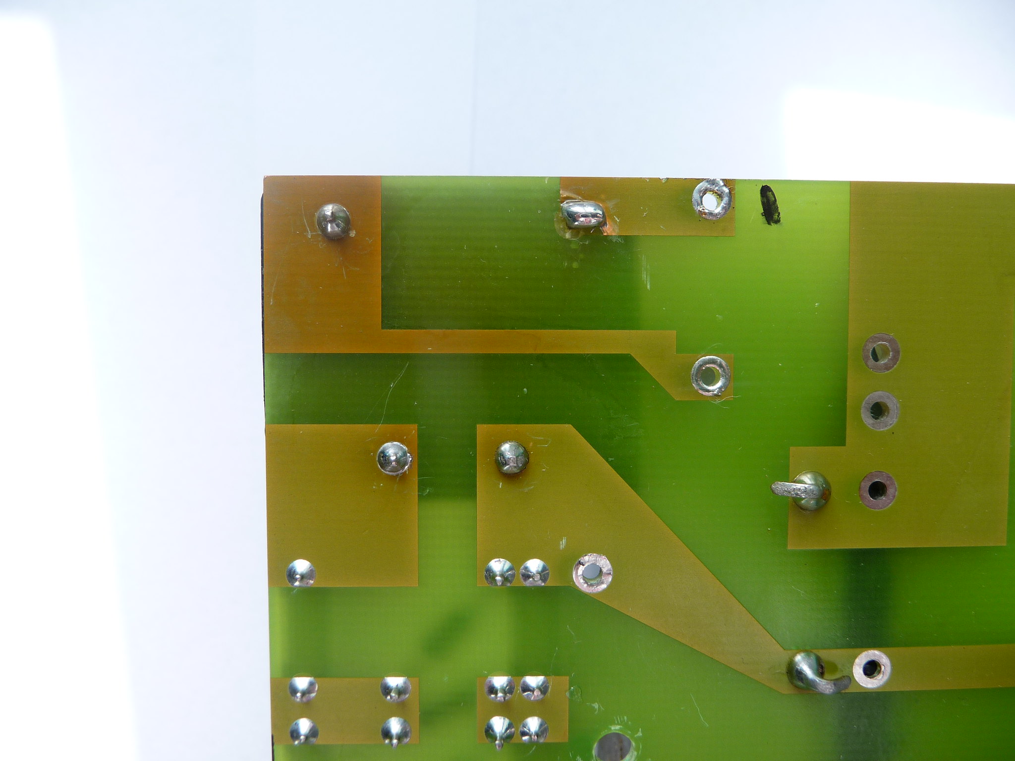 One of the transformers 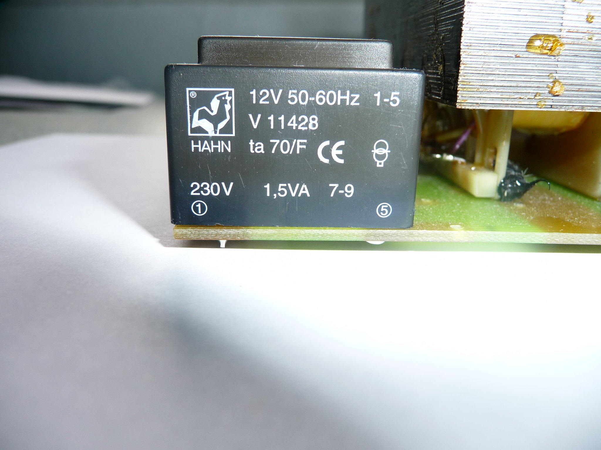 When dismantling the Right board the air core inductor fell off LOL  - will deal with that later 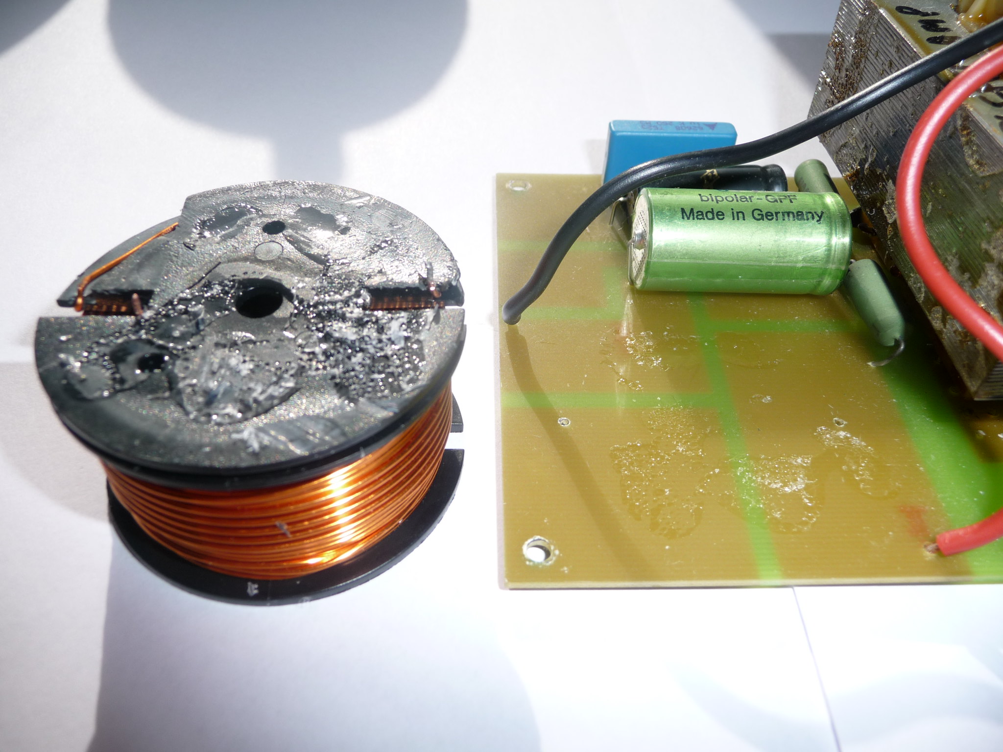 What would cause the input transformers to get so hot to discolour & fail? The question now is - do I replace both input transformers with identical like for like or is there an alternative that may not get so hot? I have found what looks like a direct replacement from the following link: www.banzaimusic.com/Hahn-BVEI3022022.htmlIs this my best bet or do you recommend something else? Cheers Chris |
|
solderdude
Administrator
measureutternutter
Posts: 4,887
|
Post by solderdude on Jul 27, 2015 20:11:36 GMT
What would cause the input transformers to get so hot to discolour & fail? The transformers used are designed to have 230V on the primary side and must deliver 12V under a 1.5W load. They are not designed to be used in the other 'direction' even though this is possible. As you measured the good one has 330V out instead of 230V out which means 1.4x the nominal value. Therefore it is more than likely that the magnetic core material is saturated which results in overheating. The question now is - do I replace both input transformers with identical like for like or is there an alternative that may not get so hot? I have found what looks like a direct replacement from the following link: www.banzaimusic.com/Hahn-BVEI3022022.htmlIs this my best bet or do you recommend something else? Cheers Chris As you can see they cost next to nothing so replacing them with this one is easy to do. However, if it were my speakers I would either use these trafo's (and replace both) + the power supply trafo I would replace with one that delivers around 12V without a load. OR (and this is perhaps easier and cheaper) replace the little trafo's with 15V versions. These won't burn out and you can use the current mains transformer. Chances are both speakers will play again. Now... there is a downside as well in this case. This is the efficiency of the stats will be lower than with the 12V trafo's. The AC out will probably be around 240V from the 15V trafos where now the voltage is 330V. This means the output voltage of the voltage multiplier will thus also be lower in the same factor. I figure the DC bias voltage will be around 2500V with the 12V trafo's and around 2000V with the 15V trafos. The efficiency of the stats will thus drop by about 2dB. This wouldn't be much of a problem when you have an active X-over for the woofer, but most likely the systym is powered by one amp. This means the woofer may be 2dB too loud now compared to when 12V trafo's are used. IF this is indeed the case the simplest (and best) solution would be to ADD another 'section' to the voltage multiplier when using the 15V trafo. Just 2 diodes + 2 capacitors are needed. Then there is the question of how good the stats still work. Some of them loose conductivity in the membrane lowering the efficiency, some loose tension which can cause distortion, arcing or sticking. That's for later and I assume if the other one plays well the second one will also be good. If the good one sounds a bit 'bass/midbass/lower mids' heavy chances are the stats need some TLC as well. I hope not so IF the 'good' one sounds good the second one may only need it's trafo replaced. |
|
solderdude
Administrator
measureutternutter
Posts: 4,887
|
Post by solderdude on Jul 27, 2015 20:14:54 GMT
I once heard full range Finals (about 30 years ago) with 2 panels bigger than a door.
Was very impressed and they sounded great.
The smaller ones were 'coloured' sounding (nothing like Quad) because of the woofer.
I have used (home made) electrostatic speakers in the past but always X'sed them over to dynamics below 300Hz.
|
|
|
|
Post by hifidez on Jul 28, 2015 10:58:00 GMT
I can add nothing constructive to this thread... just a comment or two. Firstly I am amazed at the breadth and depth of knowlege in here. Someone comes in and says "help me fix my 'statics' " and BAM! Totally pleased to be a member here. When I have heard electrostatics at hi-fi shows I'm usually impressed. Although, having said that, I haven't heard a good demo of any of the recent Quads. However, the few times I've been privileged to hear Martin Logans... wow. Also I quite like the Magneplanar approach; in case anyone doesn't know, these look like 'statics (in that they are a panel loudspeaker) but they are actually a clever variation on conventional speaker drivers which use magnets and wires. I bought an ex-demo pair of Magnepan's little SMGa. I say 'little', they are 4' tall. Paid £350 quid back in 1990. One panel has suffered a little damage due to a Musical Fidelity B200 going crazy. I reckon it put too many volts through the bass conductor wire which heated it up and caused it to part company with the bass membrane. I've managed to do a repair with some cling film. Still sounds ok. Incidentally, the crossover in the SMGa is a series circuit, not the usual parallel component arrangment. The top end of the SMGa is a marvel. Initially it sounds a little soft but it actually sounds very natural when you adjust to the fact that it shares none of the characteristic resonances that normal tweeters have. The SMGa doesn't even have the 'quasi-ribbon' tweeter that current models have, just a few folds of wire glued to a plastic sheet. It sounds so sweet and detailed. Bass extension is naturally limited in this, the smallest Maggie. But there's just enough output at 40Hz which means bass guitar is not bad, not bad at all. If you listen critically you can tell that the MDF speaker frames tend to resonate a bit and this helps the impression of fullness and warmth. Some people re-build the frames to reduce this effect but then I've heard that if you do this then they don't sound as good. My Maggies live behind my home office door. Don't bring them out to play often as I can't have them far enough out into the room to work at their best. Besides, I'm still stunned by my Spendor A5s. Taken a while back... 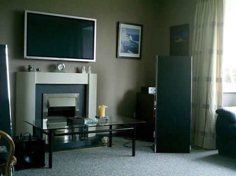 Derek |
|
Crispy
very active
Madrigal music is playing - Voices can faintly be heard, "Please leave this patient undisturbed."
Posts: 779 
|
Post by Crispy on Jul 28, 2015 12:03:35 GMT
The transformers used are designed to have 230V on the primary side and must deliver 12V under a 1.5W load. They are not designed to be used in the other 'direction' even though this is possible. So the designer has used input transformers in the wrong direction, no wonder we have problems? As you measured the good one has 330V out instead of 230V out which means 1.4x the nominal value. Therefore it is more than likely that the magnetic core material is saturated which results in overheating. Below is a pic of some of the testing instructions the guy sent me for testing NSS 03 speakers which as you can see from the schematics posted earlier are slightly different to the Finals, but it reckons output from the wall PSU should be approx 12 - 15 volts AC and the input transformer output voltage should be approx 300 - 350 Volts AC using the method in the pics below. It also reckons some units are equipped with a 230V input transformer. 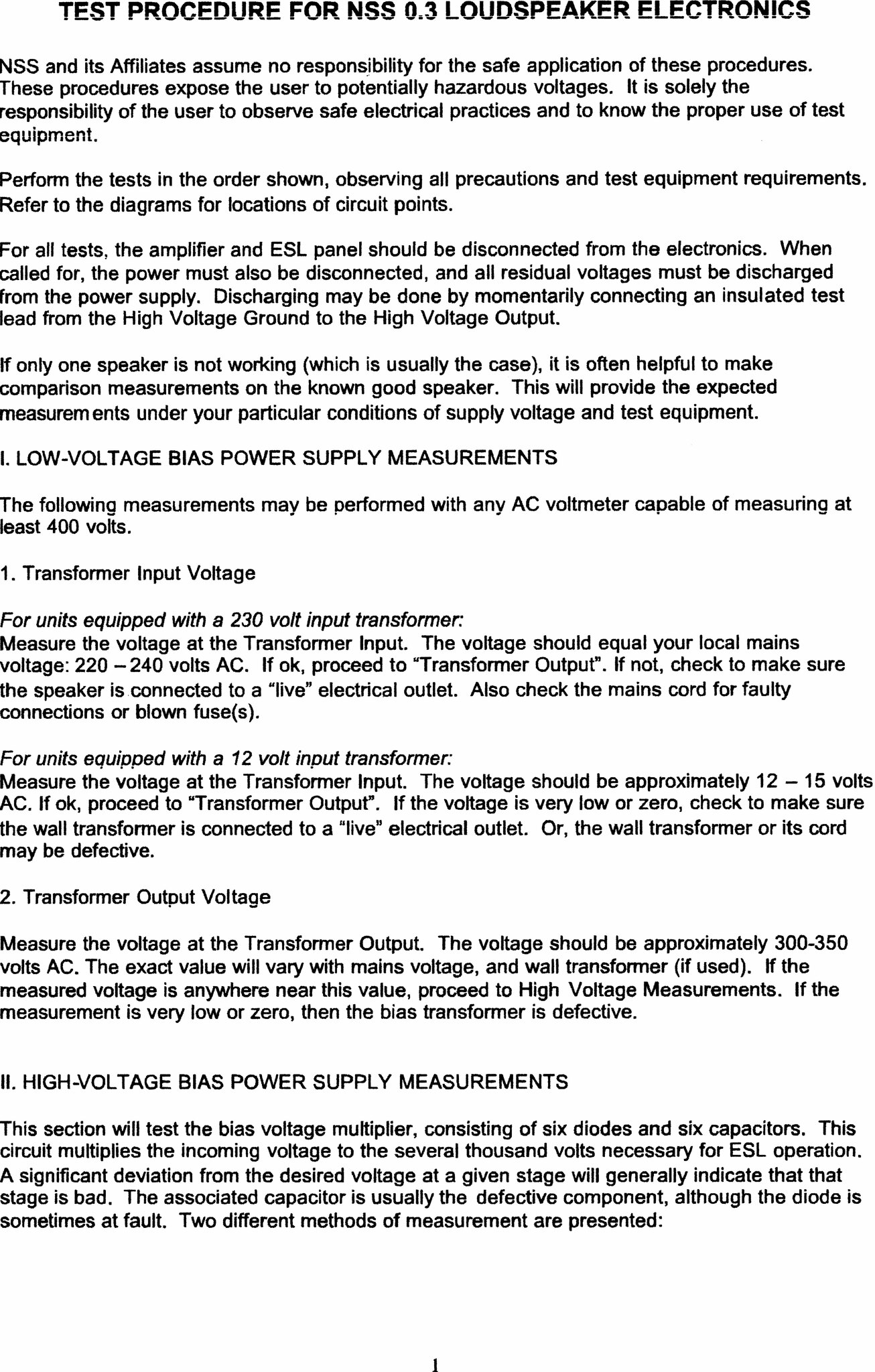 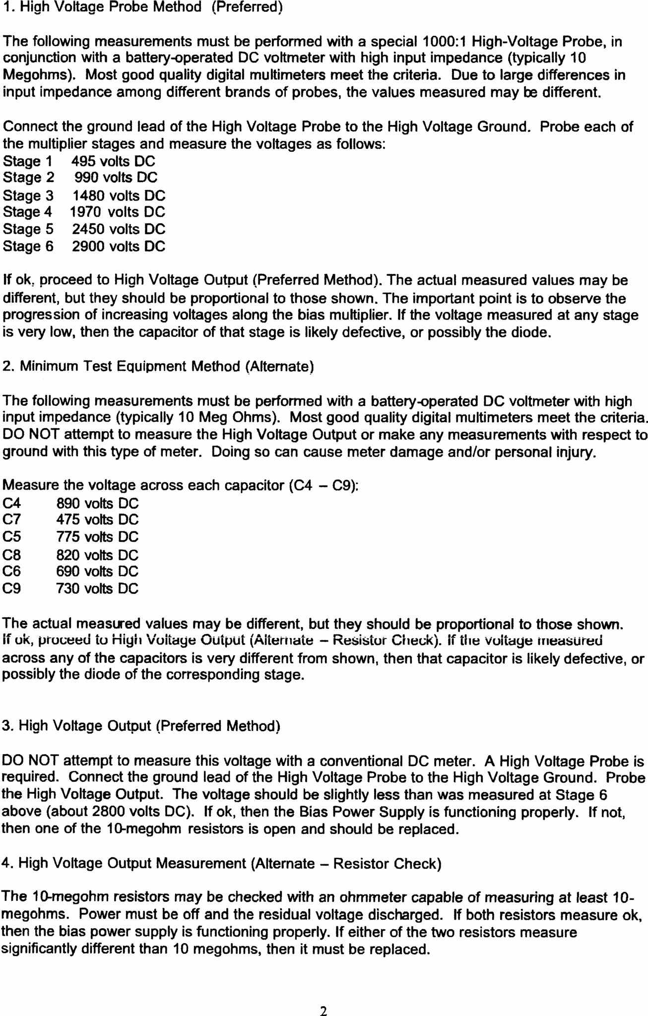 OR (and this is perhaps easier and cheaper) replace the little trafo's with 15V versions. These won't burn out and you can use the current mains transformer. The link to the little 15V traffos sends me back to my link for the original Hahn transformer.  This seems a better solution if they will not burn out and I will still be able to use the 15 V transformers. What I don't get is this bit "why would you take 230 Volts AC and turn it into 12 Volts AC via a SMPS only for the transformer in the speaker to turn it back to 230 Volts AC"? Can the transformer be omitted and be run straight from the mains? Now... there is a downside as well in this case. This is the efficiency of the stats will be lower than with the 12V trafo's. The AC out will probably be around 240V from the 15V trafos where now the voltage is 330V. This means the output voltage of the voltage multiplier will thus also be lower in the same factor. I figure the DC bias voltage will be around 2500V with the 12V trafo's and around 2000V with the 15V trafos. The efficiency of the stats will thus drop by about 2dB. This wouldn't be much of a problem when you have an active X-over for the woofer, but most likely the systym is powered by one amp. This means the woofer may be 2dB too loud now compared to when 12V trafo's are used. IF this is indeed the case the simplest (and best) solution would be to ADD another 'section' to the voltage multiplier when using the 15V trafo. Just 2 diodes + 2 capacitors are needed. According to test procudeure for NSS 03 the DC bias voltage should be around 2800 Volts DC Looking at the board Frans I cant see much room to add 2 more diodes & caps? Then there is the question of how good the stats still work. Some of them loose conductivity in the membrane lowering the efficiency, some loose tension which can cause distortion, arcing or sticking. That's for later and I assume if the other one plays well the second one will also be good. If the good one sounds a bit 'bass/midbass/lower mids' heavy chances are the stats need some TLC as well. I hope not so IF the 'good' one sounds good the second one may only need it's trafo replaced. When I first got the speakers I tried the so called good one? It worked but sounded bloody awful. Judging by the condition of the stat from the bad speaker there will definitely be some work to do on them, one of the wires is disonnected and needs re-soldering. At the moment I would just like to concentrate on getting the electronics working getting them out of the way, then I can concentrate on the cosmetics of the units and then the stats themselves. Thanks Frans |
|
Crispy
very active
Madrigal music is playing - Voices can faintly be heard, "Please leave this patient undisturbed."
Posts: 779 
|
Post by Crispy on Jul 28, 2015 12:15:23 GMT
I have used (home made) electrostatic speakers in the past but always X'sed them over to dynamics below 300Hz. Should I think about doing this while I am messing around with the electronics? if so is it a complicated job. I'm not in any hurry to sort these speakers out, my wife bought me them as a Christmas present last year and it has only taken me 7 months to pluck up the courage and attempt repairs  I think Slow but Sure - take it nice and steady one step at a time and they will soon be singing sweetly to me  |
|
Crispy
very active
Madrigal music is playing - Voices can faintly be heard, "Please leave this patient undisturbed."
Posts: 779 
|
Post by Crispy on Jul 28, 2015 12:41:03 GMT
Firstly I am amazed at the breadth and depth of knowlege in here. Someone comes in and says "help me fix my 'statics' " and BAM! Totally pleased to be a member here. Likewise Derek, somebody somewhere always has an answer - although it is usually Frans  When I have heard electrostatics at hi-fi shows I'm usually impressed. Although, having said that, I haven't heard a good demo of any of the recent Quads. However, the few times I've been privileged to hear Martin Logans... wow. That is the main reason for attempting to repair these speakers, electrostatics always sound better to my ears than conventional speakers. I bought an ex-demo pair of Magnepan's little SMGa. I say 'little', they are 4' tall. Paid £350 quid back in 1990. One panel has suffered a little damage due to a Musical Fidelity B200 going crazy. I reckon it put too many volts through the bass conductor wire which heated it up and caused it to part company with the bass membrane. I've managed to do a repair with some cling film. Still sounds ok. Incidentally, the crossover in the SMGa is a series circuit, not the usual parallel component arrangment. Thats another reason I bought this particual set of speakers, the footprint is small - almost identical to my AE1's. The reason your amp went crazy could be due to clipping? i'm no expert but ESL speakers require a lot of voltage and not wattage? it may be worth reading this white paper by Roger Sanders: sanderssoundsystems.com/technical-white-papers/52-esl-amp-white-paperMy Maggies live behind my home office door. Don't bring them out to play often as I can't have them far enough out into the room to work at their best. Besides, I'm still stunned by my Spendor A5s. That is a shame Derek, I bet when the are positioned correctly in the room they sound stunning, but another reason why I chose the Finals with a small footprint. Taken a while back...  Derek Nice set up Derek and looking closely at it the speakers do not intrude too far into your room? Chris |
|
|
|
Post by hifidez on Jul 28, 2015 13:04:25 GMT
Sorry, didn't intend to drag this so far off-topic. Yes, agreed it's usually him :-) My B200 actually failed... I then had it repaired at Hampshire Audio where I bought it. It fried both the left channel Maggie and the input stage of my then subwoofer's active crossover. True, the B200 didn't have quite enough current to drive the 4 Ohm SMGa, but the sound of the amp running out of juice was so obvious I could easily back things up a bit. That very rarely happened as one gets used to what is a safe position on the volume knob. However, one piece that often caught me out was a section in Faure's Requiem where the orchestra, organ and large choir are going at it like crazy. That tended to stretch things a bit. The B200 had plenty of Watts but not enough Amps for such a low impedance load? My present amp, the A3.2cr has plenty of current and when I do play with the Maggies all sounds in control. Very much so. That old B200 failed yet again a couple of years later. This time it burnt out an Audax Kevlar driver that was part of an IPL DIY kit speaker. Totall toasted the voice coil. In that picture from about '99 we had less furniture than now! Where the left speaker was there's now a sofa so it's not on 'fraid to say. Current set-up, near as damn-it...  |
|
solderdude
Administrator
measureutternutter
Posts: 4,887
|
Post by solderdude on Jul 28, 2015 14:31:53 GMT
What I don't get is this bit "why would you take 230 Volts AC and turn it into 12 Volts AC via a SMPS only for the transformer in the speaker to turn it back to 230 Volts AC"? Can the transformer be omitted and be run straight from the mains? In theory you could do that because the audiotransformer separates the mains from the audio circuit. A 230V to 230V trafo would have been better but these aren't as common as 230V to something lower. Another reason is a 230V trafo cannot be used on American soil... there is 115V there. Using a 12V to 230V is therefore a bit more logical because depending on the mains voltage it is always easy to go to 12V AC. The other reason why there is a transformer is to limit the inrush current and to ensure you cannot get a jolt when removing the mains cord and accidentally touching the pins shortly afterwards. So trafo's it is. No reason to saturate the magnetic cores as this is dissipated in heat anyway so 15V it is (the link brings me to the 15V version (Hahn BVEI3022023 type SKU24058) However, chances are you do not reach the sought after 300-350V any more. This is easily cured by adding another section but first I would simply replace the defective trafo with a 15V one (order 2, one for the other channel as well) Then measure the output voltage of that trafo. Based on that voltage we can see if we need to add a 'section'. According to test procudeure for NSS 03 the DC bias voltage should be around 2800 Volts DC Looking at the board Frans I cant see much room to add 2 more diodes & caps? There is always room for some caps + diodes when using some vero board .....  Might not be needed, first lets see what the 15V trafo does. And .. if that one doesn't get hot. When I first got the speakers I tried the so called good one? It worked but sounded bloody awful. Judging by the condition of the stat from the bad speaker there will definitely be some work to do on them, one of the wires is disonnected and needs re-soldering. At the moment I would just like to concentrate on getting the electronics working getting them out of the way, then I can concentrate on the cosmetics of the units and then the stats themselves. yes, first get the power supply functional and perhaps adress the stats themselves afterwards. Can you see if the membrane is still in the middle between the stators ? |
|
solderdude
Administrator
measureutternutter
Posts: 4,887
|
Post by solderdude on Jul 28, 2015 14:36:51 GMT
Should I think about doing this while I am messing around with the electronics? if so is it a complicated job. I'm not in any hurry to sort these speakers out, my wife bought me them as a Christmas present last year and it has only taken me 7 months to pluck up the courage and attempt repairs  I think Slow but Sure - take it nice and steady one step at a time and they will soon be singing sweetly to me  When the stats are a goner first attempt to open them up and see if the can be fixed. The tensioning and making them conductive is the difficult part. The stats I made do NOT have tensioned membranes at all, unique AFAIK. I used a handy trick to overcome sticking. For that reason the stats sound better (not like a drum). Won't disclose how to make them in public but can tell how to make them via PM. Is a lot of work though, not difficult... |
|
Crispy
very active
Madrigal music is playing - Voices can faintly be heard, "Please leave this patient undisturbed."
Posts: 779 
|
Post by Crispy on Jul 29, 2015 15:42:15 GMT
So trafo's it is. No reason to saturate the magnetic cores as this is dissipated in heat anyway so 15V it is (the link brings me to the 15V version (Hahn BVEI3022023 type SKU24058) Thanks for that Frans, yes the link does take you to the 15V version - I only looked at the stock photo which showed 12V  and not the description. Anyway the two 12V traffos are removed and in the bin, it looks like somebody else has had bother with them before as both boards had one lifted and torn off pads in exactly the same place. I have ordered the new 15V versions last night and got an E-Mail this morning saying dispatched  At approximately £5 each inc PP they are a bargain all the way from Berlin - I was expecting to pay a hell of a lot more for replacement traffos, I think another reason why the project was put on hold - short of funds straight after Christmas. However, chances are you do not reach the sought after 300-350V any more. This is easily cured by adding another section then measure the output voltage of that trafo. Based on that voltage we can see if we need to add a 'section'. There is always room for some caps + diodes when using some vero board .....  Might not be needed, first lets see what the 15V trafo does. And .. if that one doesn't get hot. I dont have any vero board Frans  good job that is cheap as well  yes, first get the power supply functional and perhaps adress the stats themselves afterwards. Can you see if the membrane is still in the middle between the stators ? I have stripped one of the stats down a while back mainly because I want to spray the wood coloured parts black, but I did notice that the membrane was intact in the middle between the stators. They looked grotty and I cannot say about the tensioning either, also like I mentioned earlier the wires need re-soldering. The stats I made do NOT have tensioned membranes at all, unique AFAIK. I used a handy trick to overcome sticking. For that reason the stats sound better (not like a drum). Won't disclose how to make them in public but can tell how to make them via PM. Is a lot of work though, not difficult... I am all ears Frans as this was probably the part that I was dreading the most, replacing the membrane, tensioning & making it conductive  I may not have to do anything? but I am willing to bet there is a good chance judging by the condition of the rest of the speakers. So if you don't mind sharing your unique non tensioned membranes method with me I will assess what is involved and decide if it is maybe a good option to do it your way if I need to? Obviously I will not pass on this knowldge to anybody else. Cheers Chris |
|
solderdude
Administrator
measureutternutter
Posts: 4,887
|
Post by solderdude on Jul 29, 2015 18:54:42 GMT
You need to get the bias voltage going first.
The membrane will only stick to one side when the bias voltage is present.
When you have the 15V trafos in you need to measure the AC voltage and could measure the DC voltages over the individual sections.
When that's all O.K. you can follow this procedure:
When powered off for a while:
1: connect all 3 stat wires together and leave them connected this way for an hour or so.
2: Remove the short between the stat wires after that hour(or a few hours).
3: Disconnect the woofer (if possible)
4: connect an amplifier and play music. (it should play very soft and distorted if anything does come out)
5: connect the mains.
The speakers should be starting to make sound rather quickly and become louder about equally fast for L and R
It could sound distorted but should become good within a very short while.
When it doesn't go any louder disconnect mains again and see if the speakers keep playing.
After quite some time they should start playing softer again and eventually distort.
This test tells us something about the conductivity of the membrane and state of the stats themselves.
Let's see how this works out.
|
|
Crispy
very active
Madrigal music is playing - Voices can faintly be heard, "Please leave this patient undisturbed."
Posts: 779 
|
Post by Crispy on Aug 5, 2015 19:51:09 GMT
There is some good news and some bad news Frans  First the good news - the new traffos arrived yesterday and I had some spare time to solder them in place. 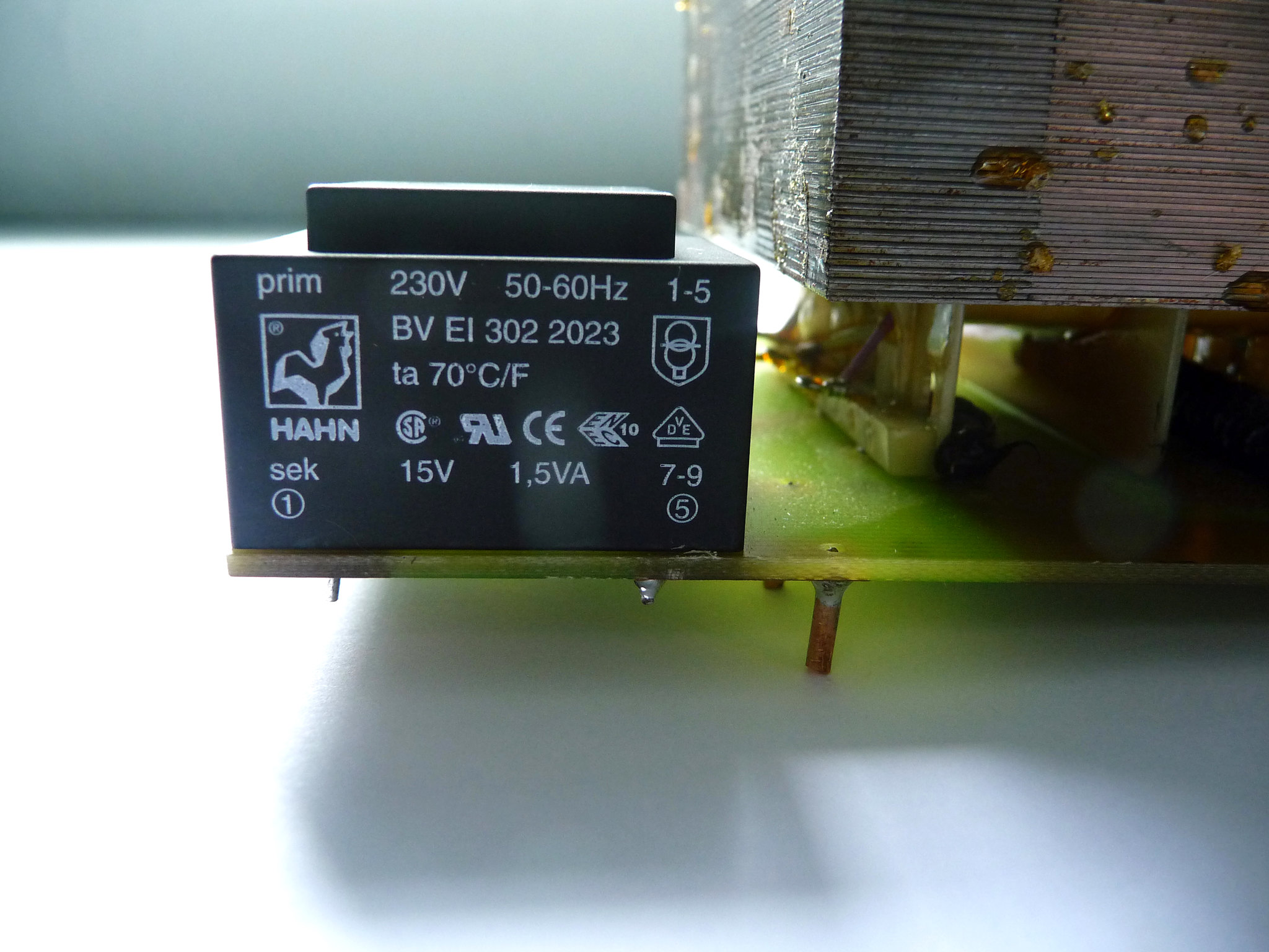 I soldered them in place thinking there would not be a problem? The bad news is that when I measured both traffos in exactly the same way as I did with the 12V versions it read: Left traffo 15V input and zero output Right traffo 15V input and zero output. After an very long think about what you said about using the traffos the wrong way around I decided to try putting the input to the output and vice versa: Result was: Left traffo 15V input and 154V output Right traffo 15V input and 152V output 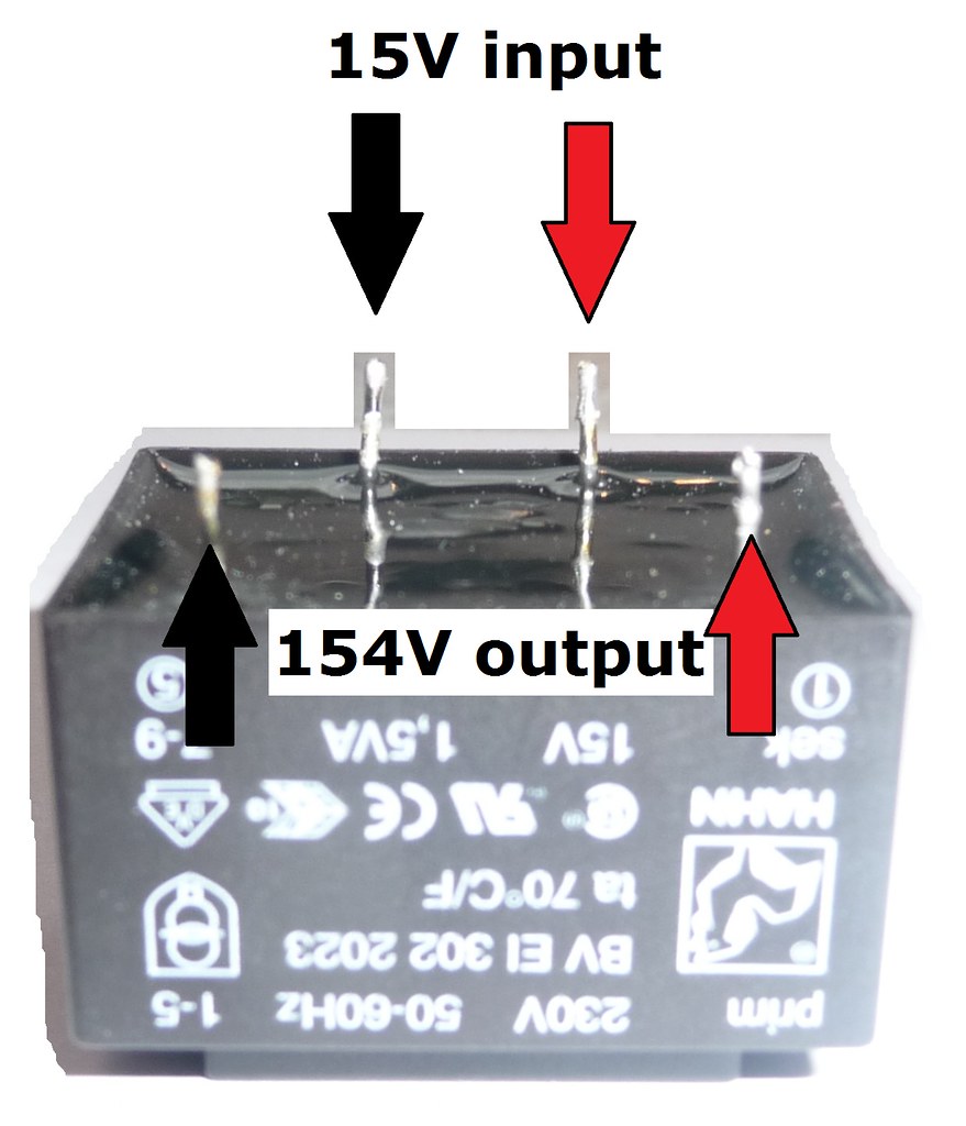 This now leaves me with the question of how do I mount the traffos wrong way around when the 10mm spacing now has to fit a 20mm spacing and vice versa? Any Ideas would be most welcome. Cheers Chris |
|