solderdude
Administrator
measureutternutter
Posts: 4,887
|
Post by solderdude on Dec 1, 2015 22:24:34 GMT
Well most electrostats do have a relatively low efficiency and can provide a 'difficult' load to amplifiers.
Mostly they tend to have very low impedances at the lowest and highest frequencies and the current is also more phase-turned compared to speakers.
Some amplifiers don't like this and may even distort or become unstable.
It generally takes an amplifier with plenty of output voltage and current capabilities to drive one properly.
With kids and cats my stats became decorations in my 'tinkering room' and haven't been playing for the last 12 years or so.
Best sound I ever heard ... the dynamic speakers I have also aren't bad but they pale in comparison.
Some day I might use them again ... if they still work by that time.
|
|
solderdude
Administrator
measureutternutter
Posts: 4,887
|
Post by solderdude on Dec 31, 2015 12:14:10 GMT
So I did some measurements on the traffo. Didn't use a power amp, just a tone generator and an oscilloscope. Frequency range is basically 'flat' from 30Hz to 500Hz and starts to rise about + 0.1dB from 1kHz.From 10kHz upwards the output increases. 30Hz 0 dB . 500Hz 0 dB 1kHz +0.1 dB 2kHz +0.26 dB 5kHz +0.4 dB 10kHz +0.5 dB 12kHz +1.2 dB 15kHz +1.6 dB 18kHz +1.7 dB 20kHz +2 dB 22kHz +2.6 dB 25kHz +3.4 dB 30kHz + 5.5dB above this I didn't measure because the impedance became too low (basically becomes a short) So .... it seems suited for the job. gain is about 35x (at 1kHz) You have to use just 1 of the 2 of the 6V primary windings from each transformer. You need to reach 130x so 4 traffo's per speaker would be enough. From each traffo you need to parallel 1 of the 6V windings. So 4x red connected together and 4x black connected together. Make sure orange and yellow wires are isolated and cannot touch each other nor other wires. The blue and brown must be connected in series as in the drawing below:  That should do the job of making it play. Now there is the rise in frequency response. This isn't a bad thing because when the trafo's are loaded with a capacitor (the stat is a capacitor) the output will drop a bit. Also as the 230V windings are in series the inductance may play a role. Maybe you should consider having a resistor (10W !) of around 1 to 2.2 Ohm in series with the (combined) red wire. Would try it this way first. It'll probably work just fine. No idea how long the transformers will work properly. With 20V AC max there will be 700V across each 230V winding (theoretically) but in practice may be lower. Most traffo's need to pass a 1000V insulation test so it may work well for a long time. |
|
Crispy
very active
Madrigal music is playing - Voices can faintly be heard, "Please leave this patient undisturbed."
Posts: 779 
|
Post by Crispy on Jan 1, 2016 16:18:57 GMT
So I did some measurements on the traffo. Didn't use a power amp, just a tone generator and an oscilloscope. Frequency range is basically 'flat' from 30Hz to 500Hz and starts to rise about + 0.1dB from 1kHz.From 10kHz upwards the output increases. 30Hz 0 dB . 500Hz 0 dB 1kHz +0.1 dB 2kHz +0.26 dB 5kHz +0.4 dB 10kHz +0.5 dB 12kHz +1.2 dB 15kHz +1.6 dB 18kHz +1.7 dB 20kHz +2 dB 22kHz +2.6 dB 25kHz +3.4 dB 30kHz + 5.5dB above this I didn't measure because the impedance became too low (basically becomes a short) So .... it seems suited for the job. Thanks Frans for taking the time to measure the traffo for me, although the measurments don't mean much to me it is very reassuring to know they will be suitable to finish the job  You need to reach 130x so 4 traffo's per speaker would be enough. Just one query on this Frans? earlier in this thread you suggested 6 traffos would be needed? has this changed with the new measurements? You need about 130V and must use an even amount of trafo's. with 6 trafo's the output voltage should be around 150V which will be fine. Do you have enough space for 6 of them ? With 4 of them the output voltage will be around 100V which may be a bit too low. Maybe you should consider having a resistor (10W !) of around 1 to 2.2 Ohm in series with the (combined) red wire. Would try it this way first. It'll probably work just fine. No idea how long the transformers will work properly. With 20V AC max there will be 700V across each 230V winding (theoretically) but in practice may be lower. Most traffo's need to pass a 1000V insulation test so it may work well for a long time. Ok, I will order some 10W 2.2Ohm resistors at he same time as the Traffo's. Info on the traffos say they have a dielectric strength of 4200VRMS? which again does not mean much to me. Another quick question Frans, do you think these traffos would generate a lot of heat and would any heat be a problem? |
|
solderdude
Administrator
measureutternutter
Posts: 4,887
|
Post by solderdude on Jan 2, 2016 12:02:19 GMT
So .... it seems suited for the job. Thanks Frans for taking the time to measure the traffo for me, although the measurments don't mean much to me it is very reassuring to know they will be suitable to finish the job  [/quote] The frequency response would be mostly flat basically. Just one query on this Frans? earlier in this thread you suggested 6 traffos would be needed? has this changed with the new measurements? The problem with traffos is that unloaded they behave differently than when loaded. Also traffos work somewhat different when used reversed which is what we are doing here. Numbers of transformers are given under resistive load where in this case there is a capacitive load. The load get's 'heavier' as the ferquency increases. So based on measurements under expected loads 4 traffos will be close to the original one which is needed to balance the stat's output to the woofer output. Ok, I will order some 10W 2.2Ohm resistors at he same time as the Traffo's. Info on the traffos say they have a dielectric strength of 4200VRMS? which again does not mean much to me. It means they were tested to withstand 4200VRMS between the primary and secondary winding. This doesn't mean the primary winding (230V) may have 4200V across it. Mostly a short 1kV peak or 2kV peak doens't ruin the trafo Another quick question Frans, do you think these traffos would generate a lot of heat and would any heat be a problem? The trafo = 15W. Each winding can handle 1.25A continuous (at 6V) = 7.5W. As it has 2 windings 2x7.5W = 15W Now there are 4 traffos each capable of 1.25A continuous = 5A continuous = 30W. BUT these currents will not flow there continuously as music signals are dynamic. The trafo's themselves (the magnetic core) can even handle 60W (4x15W). When you play music at 60W average 600W peaks would need to be present which the amp cannot provide so the trafo's may run 'warm' when playing loud over a lengthy time (hours) |
|
Crispy
very active
Madrigal music is playing - Voices can faintly be heard, "Please leave this patient undisturbed."
Posts: 779 
|
Post by Crispy on Jan 2, 2016 19:22:27 GMT
So based on measurements under expected loads 4 traffos will be close to the original one which is needed to balance the stat's output to the woofer output. Well that is good news only having to buy 4 rather than 6  also they will fit in the enclosures better as you can probably see from the picture below. I have made a little more progress and soldered the boards and fitted them back on the bases ready for the Traffos. Once the traffos are in place and all the elctronics tested then the bases will be getting a spray job   When you play music at 60W average 600W peaks would need to be present which the amp cannot provide so the trafo's may run 'warm' when playing loud over a lengthy time (hours) That is also good news as I rarely play Loud for extended periods. |
|
Crispy
very active
Madrigal music is playing - Voices can faintly be heard, "Please leave this patient undisturbed."
Posts: 779 
|
Post by Crispy on Jan 28, 2016 19:07:08 GMT
I have made a little progress and managed to get 4 traffo's rigged up and almost ready for testing - just need to mend my amp first  3 more traffos are on back order, so I am waiting for them to arrive. I am also going to double and triple check the wiring as it started to get a bit confusing and I ended up marking each traffo with small cable ties to identify them, which then made it easier? I am also going to check again that thay will still fit in the enclosures? 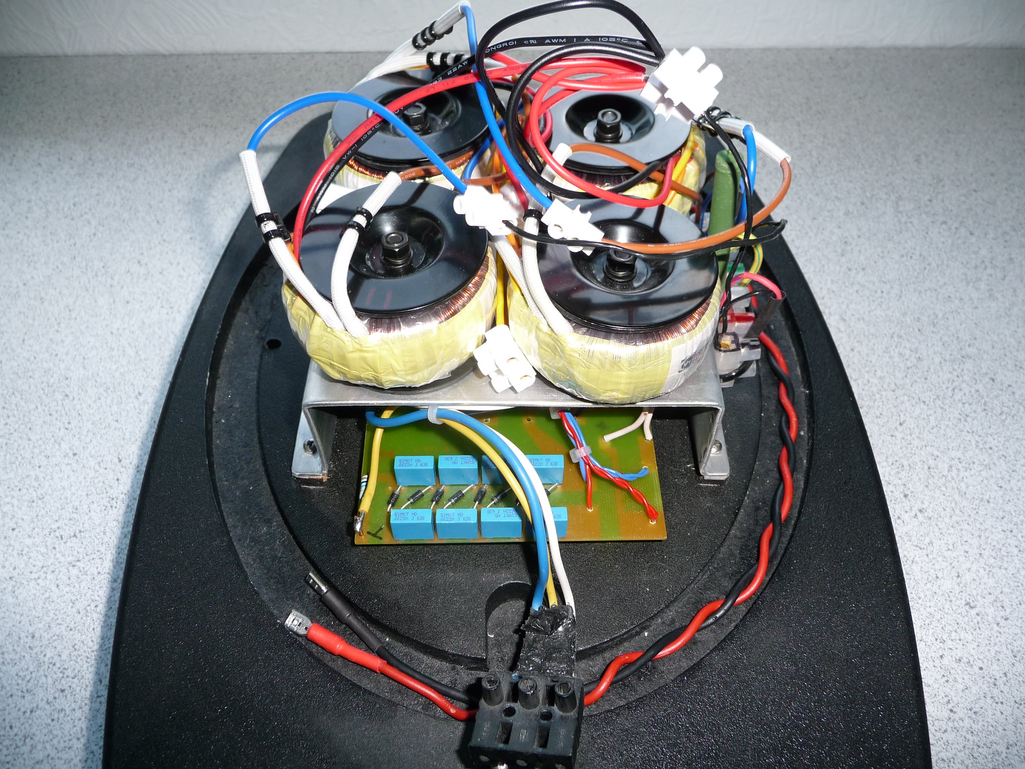 Fran's I have temporarily isolated the wires that you said with terminal blocks - when I get around to doing everything for real, what would be a good way of terminating the leads so that they are less bulky. I thought maybe shortening the wires and bending them over and covering them with heatshrink? |
|
Crispy
very active
Madrigal music is playing - Voices can faintly be heard, "Please leave this patient undisturbed."
Posts: 779 
|
Post by Crispy on Sept 15, 2016 20:01:23 GMT
Where does the time Go? I cannot believe it was January when I last did some work on my ESL's  I managed to test the electronics from both speakers and the result is below: LEFT SPEAKER: 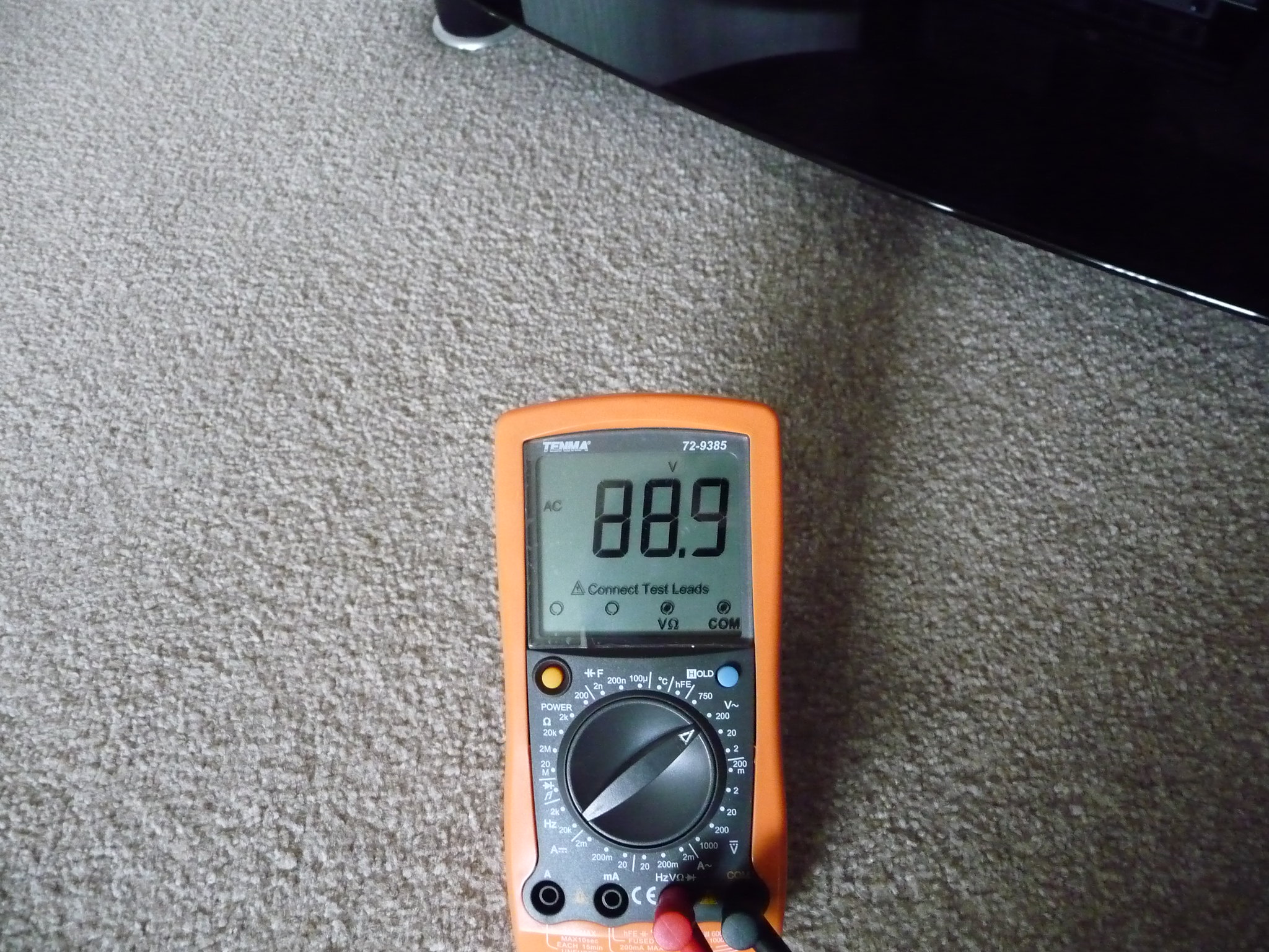 RIGHT SPEAKER: 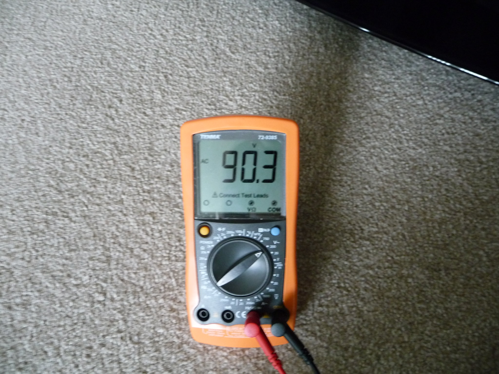 As you can see from this Frans, it is a bit short of 130V needed to drive them properly, so I modified the drawing you posted for the 4 traffo combination to make a 6 traffo combination, could you please have a quick look at it and advise me if it is correct? 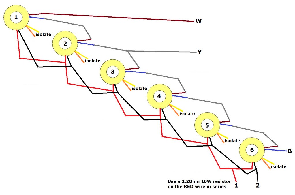 Thanks Chris |
|
solderdude
Administrator
measureutternutter
Posts: 4,887
|
Post by solderdude on Sept 15, 2016 21:24:57 GMT
Yes, the drawing is correct.
The difference in output voltage is just 3dB though.
You could try how it sounds now before using more traffo's
|
|
Crispy
very active
Madrigal music is playing - Voices can faintly be heard, "Please leave this patient undisturbed."
Posts: 779 
|
Post by Crispy on Sept 17, 2016 18:58:35 GMT
Yes, the drawing is correct. The difference in output voltage is just 3dB though. You could try how it sounds now before using more traffo's Okies Frans, I will try to find some time and get the one working? panel out of the loft and pair it up with the electronics and give it a whirl? is 3db a lot of difference to the sound? |
|
solderdude
Administrator
measureutternutter
Posts: 4,887
|
Post by solderdude on Sept 17, 2016 21:30:12 GMT
3 dB is audible.
Worst case scenario you have a nice bass boost.
|
|
Crispy
very active
Madrigal music is playing - Voices can faintly be heard, "Please leave this patient undisturbed."
Posts: 779 
|
Post by Crispy on Jan 23, 2018 10:27:42 GMT
I decided that I will finish these speakers this year  I ordered 4 more transformers to try and get the voltage up near the original 130. Below is a picture of the units with the extra 4 traffos in place and ready for testing, also had the time to strip the crap paint off the bases - so they are now ready for a paint job  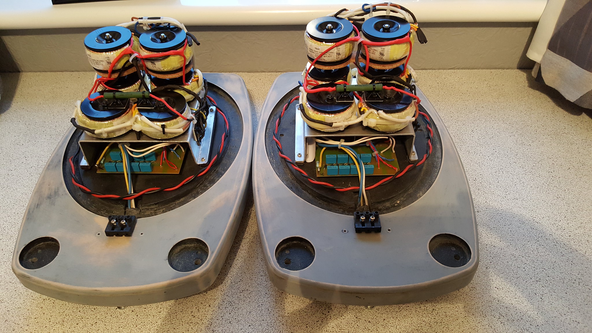 It looks a bit crude but here is one unit ready for testing.  Left hand unit gave a reading of 124.1 which is a lot closer to the original. with 4 traffos 88.9 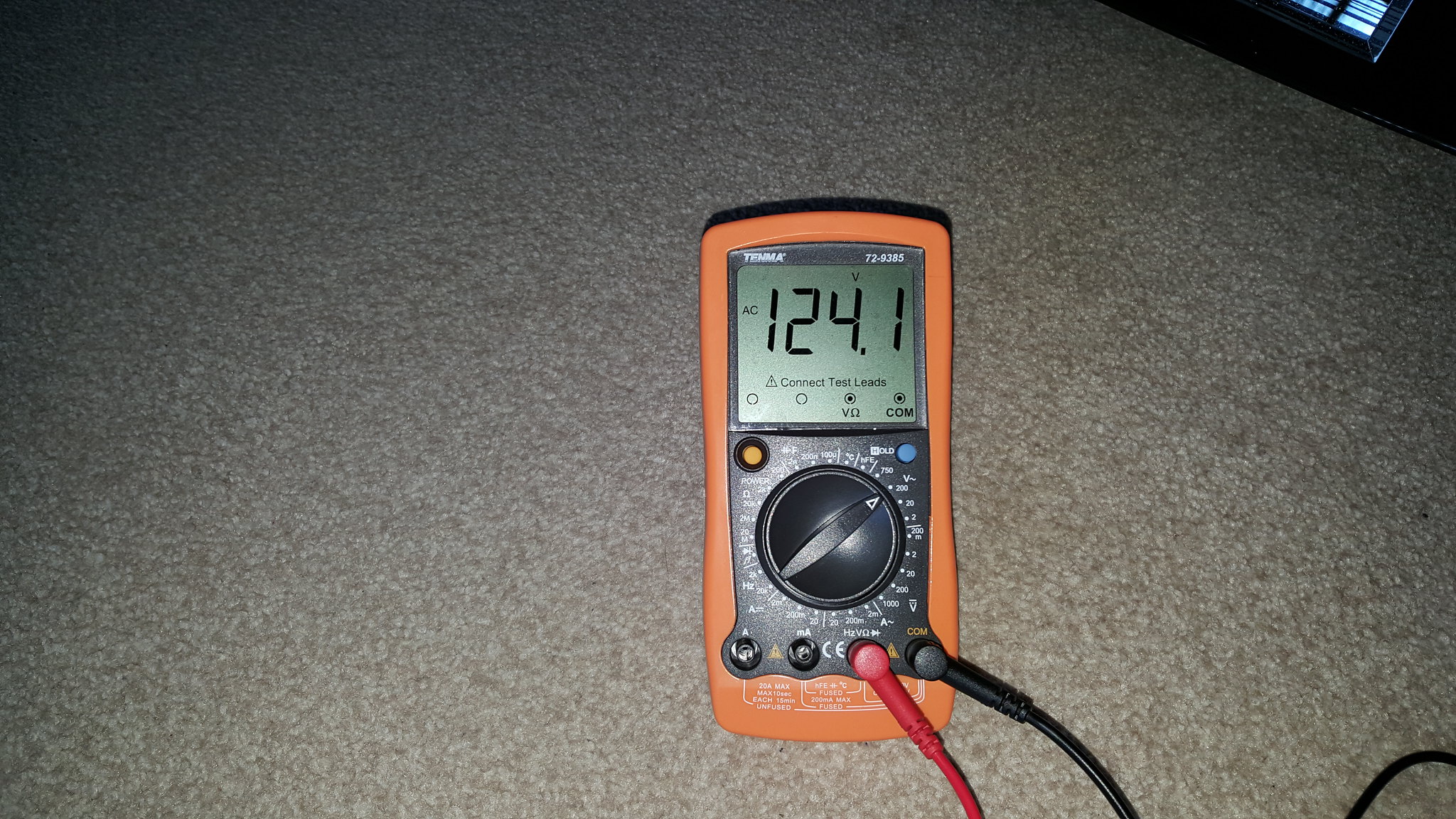 Right hand unit gave an even better reading at 126  with 4 traffos 90.3. So I am happy with these readings as they are about as close as I am going to get to the original 130. 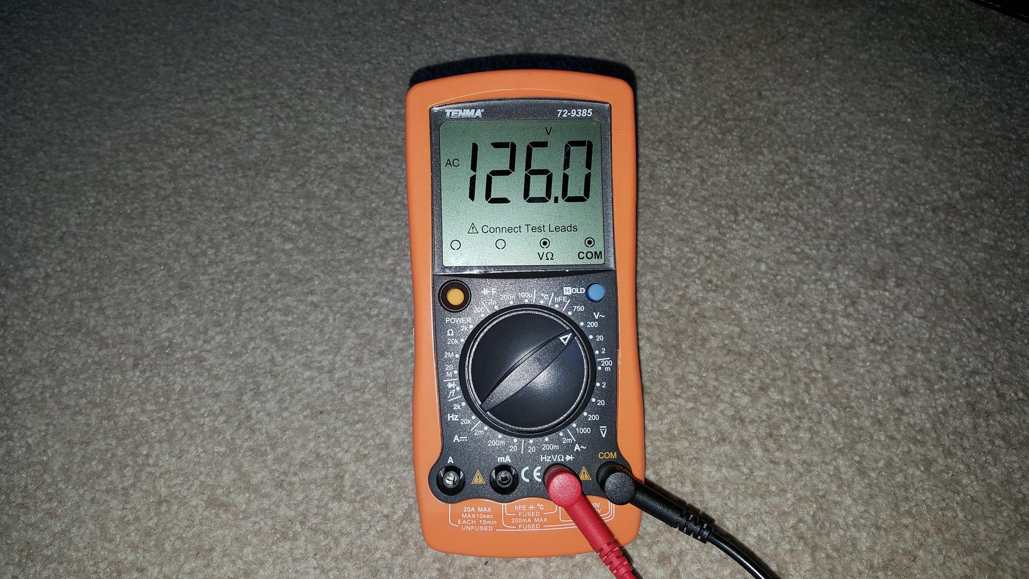 While I was at it, I thought I would put them together and have a quick listen  not a chance in hell. What I thought was the good working ESL panel was not and as you can see from the pic one of the wires is completely pulled out, so more work.  So my priority at the moment is to finish painting the bases and bass cabinets and then mend the ESL panels. Frans, while I had the ESL panels out I had a quick look at the membranes - they did not look too bad? but who am I to know what is good. They also did NOT look they were tensioned but again difficult to know from an untrained eye  |
|
solderdude
Administrator
measureutternutter
Posts: 4,887
|
Post by solderdude on Jan 27, 2018 7:52:34 GMT
The membranes must have mechanical tension on it.
When the panel is lying flat the membrane must not sag to the point where it touches a stator.
If it does you have to tension it again.
When it can touch the stators it will surely 'stick' to one of the stators when putting the high bias voltage on there.
AC voltages are good.
There is only a 0.13dB level difference.
Looks like one of the stator wires is loose.
|
|
Crispy
very active
Madrigal music is playing - Voices can faintly be heard, "Please leave this patient undisturbed."
Posts: 779 
|
Post by Crispy on Jan 29, 2018 20:55:40 GMT
The membranes must have mechanical tension on it. When the panel is lying flat the membrane must not sag to the point where it touches a stator. If it does you have to tension it again. When it can touch the stators it will surely 'stick' to one of the stators when putting the high bias voltage on there. AC voltages are good. There is only a 0.13dB level difference. Looks like one of the stator wires is loose. Thanks Frans, I will have another look in the not too distant future - my main priotity now is to spray paint the bases and bass bins already to accept the ESL panels. I could not find any cling film so used baking foil to cover the elctronics - here they are after a few coats of primer all ready to go in the oven  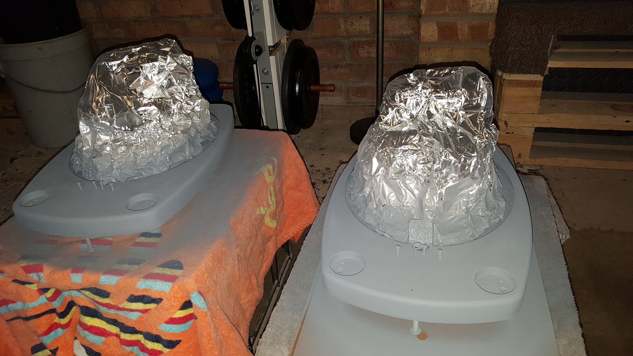 I started to strip one of the bass bins and wish I had never started - what a job. I think I will have to look at some paint stripper. 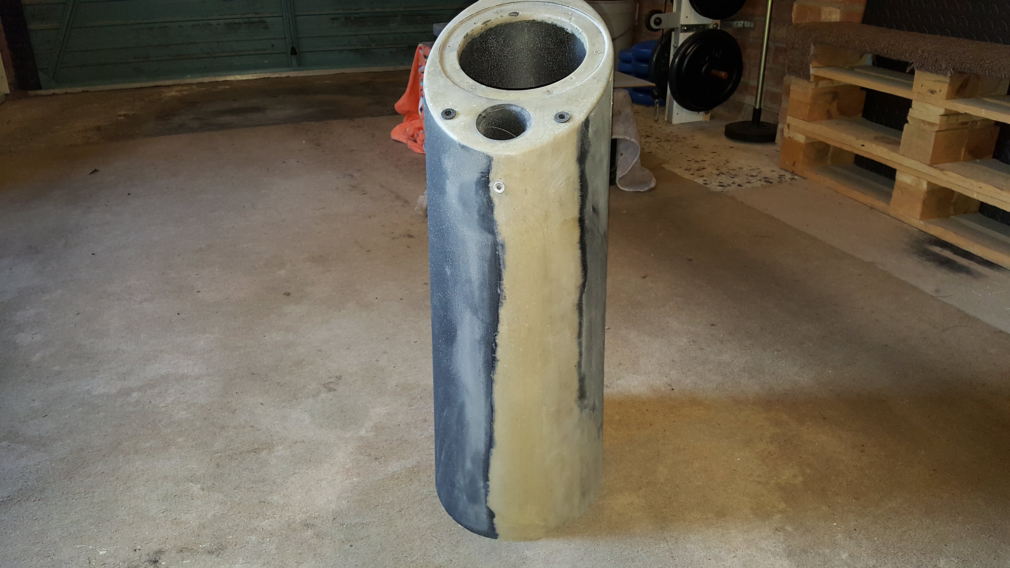 This is one of the ESL frames that I sprayed last year. It looks good in real life but the picture makes it look crap. 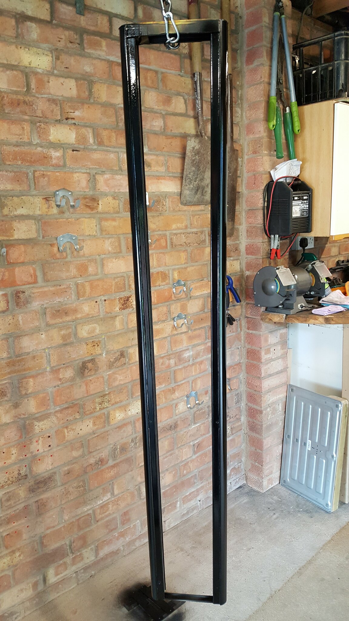 I have a question for you Frans about the bass bins, you will see from the pics that they have a bass port, but then block it up with a plastic plug? I dont get this? 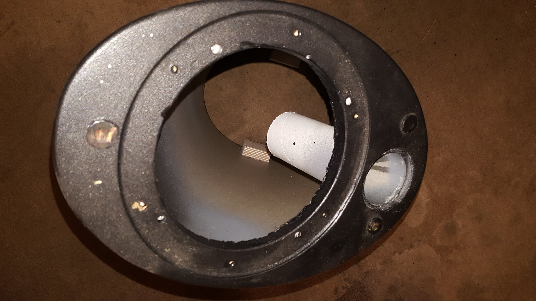 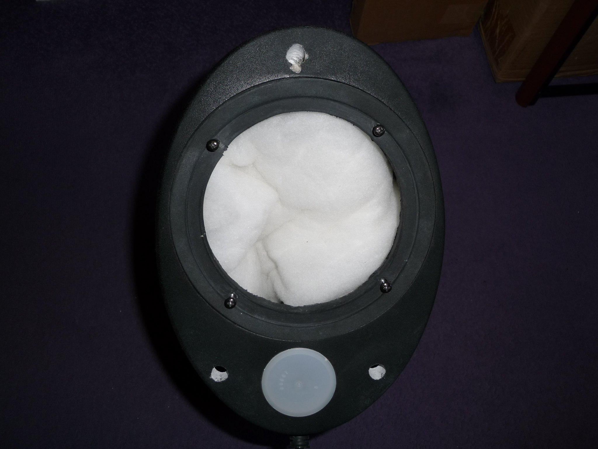 Also the bass cones have a dent in the middle - does this affect the sound or is it more cosmetic? They will probably need some new gaskets as well - any idea where I can get some? 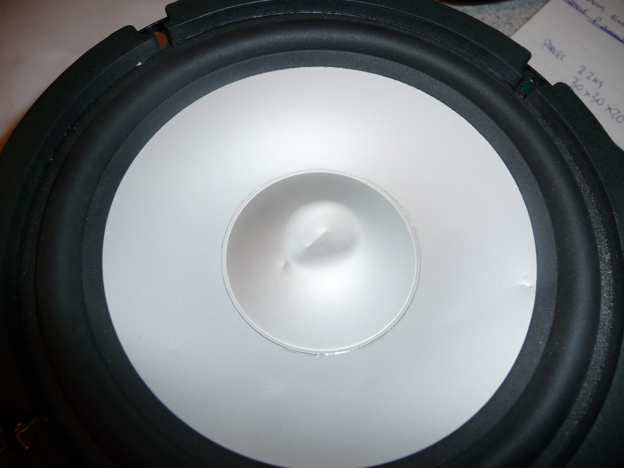 |
|
solderdude
Administrator
measureutternutter
Posts: 4,887
|
Post by solderdude on Jan 29, 2018 22:31:09 GMT
unless the foam is decayed or torn no new rings are needed.
I don't think the dents will be audible.
You can try to pop the dent out with a vacuum cleaner.
Just make sure you can regulate the suction force with the vent in the 'pistol' otherwise you may inflict more damage.
|
|