solderdude
Administrator
measureutternutter
Posts: 4,887
|
Post by solderdude on Aug 5, 2015 21:15:41 GMT
Usually the wider spaced pins are for the higher voltage, which is the same here.
1-5 = 230V
What's strange though is that with 15V input one would expect an output voltage closer to 230V instead, it is half of the earlier measured 300V.
Using a lower voltage trafo will lead to overheating so here is what I would propose.
Buy another set of trafos.
Use 2 of them for each speaker (they are small, try to find some space)
As it is now I would use 2 trafo's per speaker by paralleling the 15V windings and putting the 'primary windings' (now actually the secondary windings) in series.
This way the trafos do not overheat and you have the earlier measured 300V.
It looks like the Hahn trafos are indeed odd in that the 12V is primary (and spaced further apart) and the 230V has pins closer together.
You just have to find a spot for both trafos.
Oh... one tip when going for the 2 trafo route.
When the 150V outputs are connected in series they have to be in phase.
When they are you get the desired 300V, when they are in counterphase you get 0V.
|
|
|
|
Post by drumdrym on Aug 6, 2015 14:07:20 GMT
Hi Chris,
enjoy following your exploits, if you wish I can do a more compact layout of the caps and diodes
on a bit of good quality FR4 pushing them as far left as possible that would let you mount the
two 15v/12v traffos side by side on the right hand side of the new extension board and
also incorporate any improvements to the circuit Frans would have in mind.
Mount the new ext board on top of original one with PCB stand offs.
Happy to make you two off nae bother mate.
Regards,
Alan
|
|
Crispy
very active
Madrigal music is playing - Voices can faintly be heard, "Please leave this patient undisturbed."
Posts: 779 
|
Post by Crispy on Aug 6, 2015 19:13:12 GMT
Hi Chris, enjoy following your exploits, if you wish I can do a more compact layout of the caps and diodes on a bit of good quality FR4 pushing them as far left as possible that would let you mount the two 15v/12v traffos side by side on the right hand side of the new extension board and also incorporate any improvements to the circuit Frans would have in mind. Mount the new ext board on top of original one with PCB stand offs. Happy to make you two off nae bother mate. Regards, Alan That is a very kind offer Alan  I know you like to follow my little dabblings into the unknown (well for me it is)  I will wait to see what Frans says about the picture I'm about to post and if your way is better then how can I refuse such a generous offer. Thanks mate. Cheers Chris |
|
Crispy
very active
Madrigal music is playing - Voices can faintly be heard, "Please leave this patient undisturbed."
Posts: 779 
|
Post by Crispy on Aug 6, 2015 19:28:32 GMT
Usually the wider spaced pins are for the higher voltage, which is the same here. 1-5 = 230V What's strange though is that with 15V input one would expect an output voltage closer to 230V instead, it is half of the earlier measured 300V. Using a lower voltage trafo will lead to overheating so here is what I would propose. Buy another set of trafos. Use 2 of them for each speaker (they are small, try to find some space) Frans, I have taken into account what you said about finding space and came up with this solution. I have used the old 12V traffos purely to see what you think and mounted them temporarily with cable ties on the other transformer - would this be a problem? 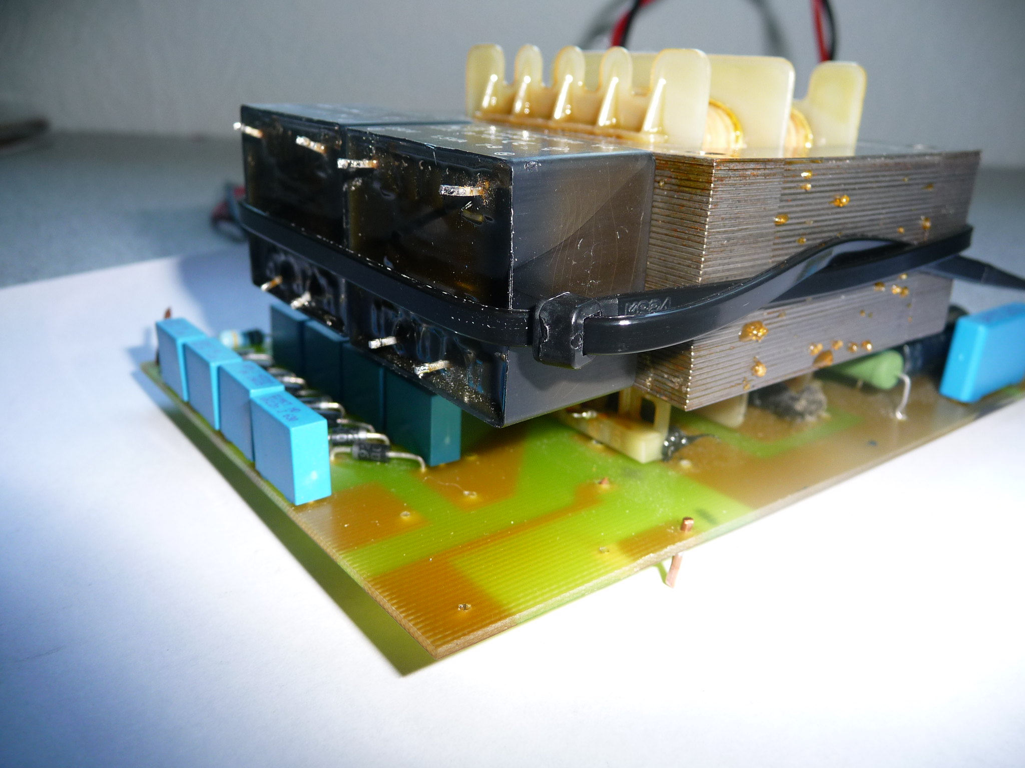 If it is not a problem then I will mount the 15V properly with some very strong double sided tape that I have and then cable tie them for good measure. As it is now I would use 2 trafo's per speaker by paralleling the 15V windings and putting the 'primary windings' (now actually the secondary windings) in series. This way the trafos do not overheat and you have the earlier measured 300V. It looks like the Hahn trafos are indeed odd in that the 12V is primary (and spaced further apart) and the 230V has pins closer together. You just have to find a spot for both trafos. Oh... one tip when going for the 2 trafo route. When the 150V outputs are connected in series they have to be in phase. When they are you get the desired 300V, when they are in counterphase you get 0V. I tried to de-chypher what you said and came up with this drawing which is probably all wrong? bear in mind the pic shows the 12V traffos.  Anyway I am all ears on what you think - especially what Alan suggested. Regards Chris |
|
solderdude
Administrator
measureutternutter
Posts: 4,887
|
Post by solderdude on Aug 6, 2015 22:05:16 GMT
I would use a block of insulating material between the audio trafo and the small ones.
Preferably something plastic or so.
Then you would have to wire differently.
The 15V inputs must go on the right side ((where you have now written 300V).
They do have to be connected in parallel just like you have drawn, except in the other holes (the holes spaced further apart)
The 230V (1-5) of the new trafos will be on the top side (like the trafos are mounted now) but will have to be connected differently:
connect the top left pin of the left trafo to the spot, where you have now drawn, the red 15V wire.
Then connect the right pin of the left trafo to the left pin of the right trafo (so just a short wire connecting the upper windings of both small trafos)
Then connect the top right pin of the right trafo to the hole which is now marked 'black wire, 15V input'.
Once done you should measure 15V on both small trafos (on the pins closest to each other) and about 150V across the top pins of each trafo.
When you measure AC from the top left pin of the left trafo to the top right pin of the right trafo you should measure about 300V there.
|
|
Crispy
very active
Madrigal music is playing - Voices can faintly be heard, "Please leave this patient undisturbed."
Posts: 779 
|
Post by Crispy on Aug 8, 2015 7:36:40 GMT
I would use a block of insulating material between the audio trafo and the small ones. Preferably something plastic or so. Just out of curiosity Frans why use plastic over say wood or alloy and what is the material insulating from? My quick solution is to use some spare plastic dividers that came with a parts storage box, cut down a bit they look like they will do the job - they are about 1-2mm thick. What do you think? 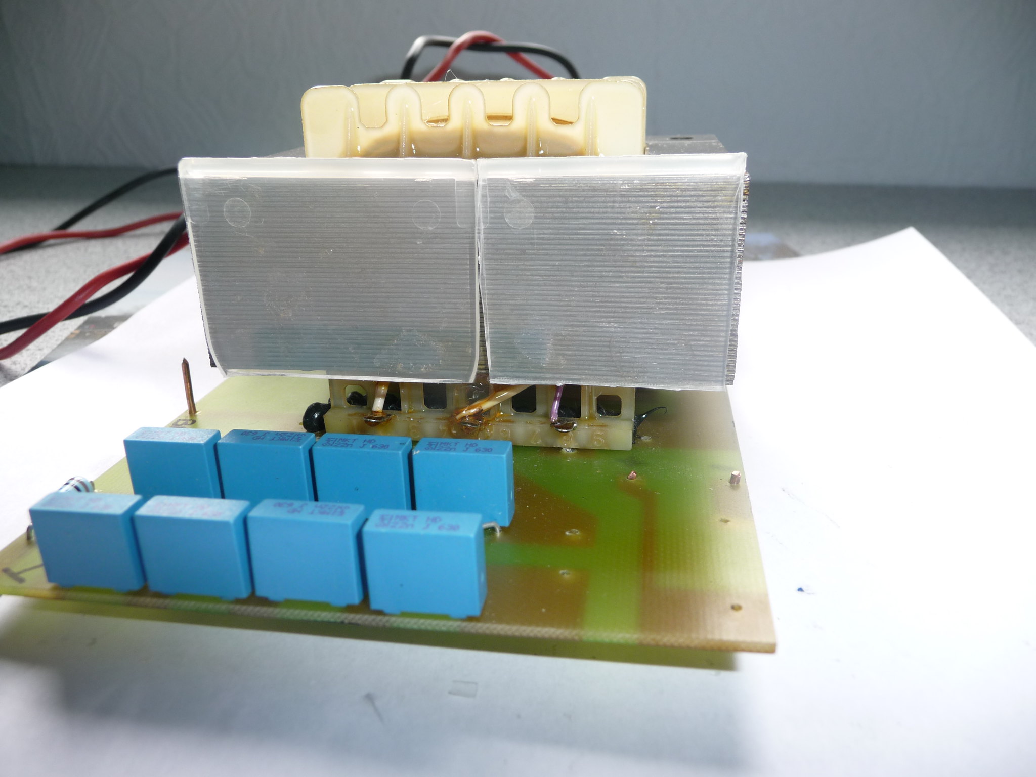 Then you would have to wire differently. The 15V inputs must go on the right side ((where you have now written 300V). They do have to be connected in parallel just like you have drawn, except in the other holes (the holes spaced further apart) The 230V (1-5) of the new trafos will be on the top side (like the trafos are mounted now) but will have to be connected differently: connect the top left pin of the left trafo to the spot, where you have now drawn, the red 15V wire. Then connect the right pin of the left trafo to the left pin of the right trafo (so just a short wire connecting the upper windings of both small trafos) Then connect the top right pin of the right trafo to the hole which is now marked 'black wire, 15V input'. Once done you should measure 15V on both small trafos (on the pins closest to each other) and about 150V across the top pins of each trafo. When you measure AC from the top left pin of the left trafo to the top right pin of the right trafo you should measure about 300V there. You're absolutely right again Frans, I did as instructed and tested the traffos off the board with jumper wires and this was the result: 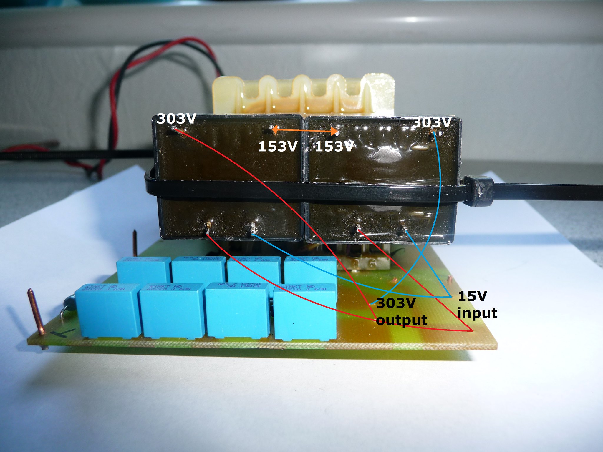 As expected the output now is back to roughly where it should be  Also out of curiosity I have noticed there is no fuse protection anywhere on the boards - would it be a good idea to fit one in somewhere? Next step is to order two more traffos for the right amp and if everything is ok get them fixed in and tested. Thanks Chris |
|
solderdude
Administrator
measureutternutter
Posts: 4,887
|
Post by solderdude on Aug 9, 2015 7:27:43 GMT
Looks good Chris !
A fuse is needed if high currents can flow when something goes wrong.
High currents with high voltages = heat (fire)
When a current increases above a certain point the fuse blows to interrupt that current.
In the case of this power supply there are just 2 1.5W trafos (used to be 1) which will limit currents by properties.
The maximum current is determined by the little trafo feeding the small ones.
If I were to mount a fuse somewhere it would be in the mains part of the trafo that feeds the (both) speakers.
Do the 2 trafos even get slightly warm during normal operation ? (a small temp increase is normal)
|
|
Crispy
very active
Madrigal music is playing - Voices can faintly be heard, "Please leave this patient undisturbed."
Posts: 779 
|
Post by Crispy on Aug 10, 2015 17:39:03 GMT
Looks good Chris ! A fuse is needed if high currents can flow when something goes wrong. High currents with high voltages = heat (fire) When a current increases above a certain point the fuse blows to interrupt that current. In the case of this power supply there are just 2 1.5W trafos (used to be 1) which will limit currents by properties. The maximum current is determined by the little trafo feeding the small ones. If I were to mount a fuse somewhere it would be in the mains part of the trafo that feeds the (both) speakers. Do the 2 trafos even get slightly warm during normal operation ? (a small temp increase is normal) If I am reading this correctly the board does not really need a fuse to protect it? I have mouted the two traffos for real in the left amplifier board: I used a thinner wire for the input so that I could get both wires into the hole and a thicker wire for the higher voltage output. 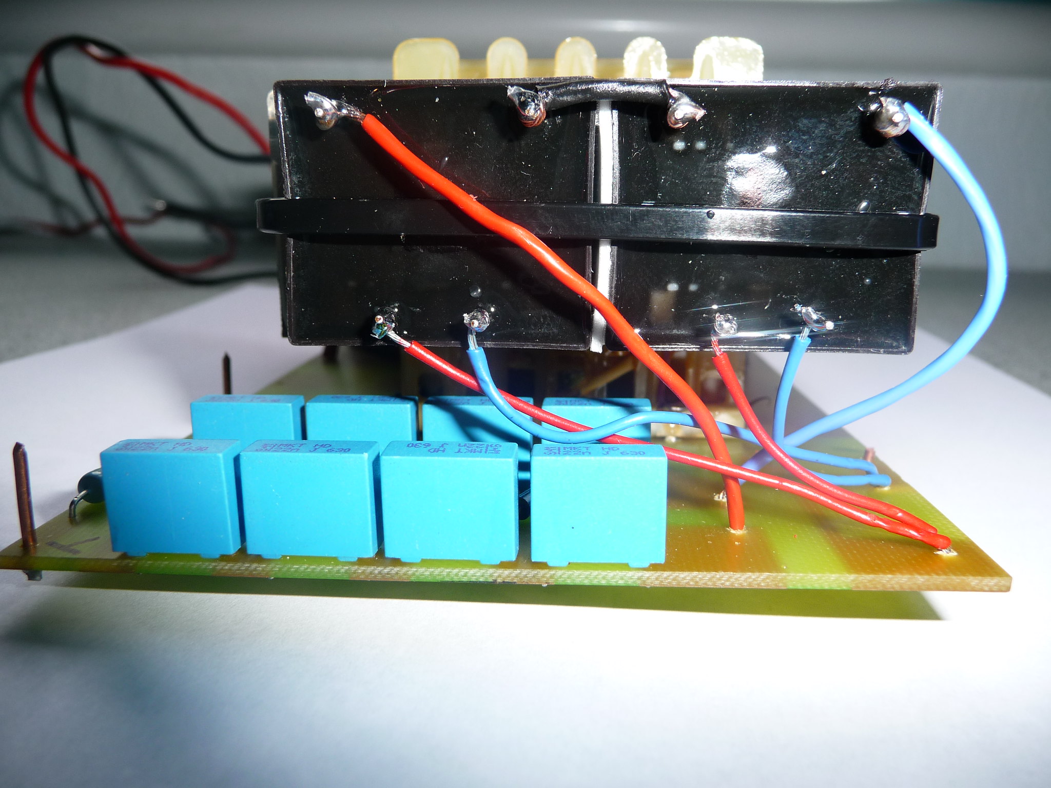 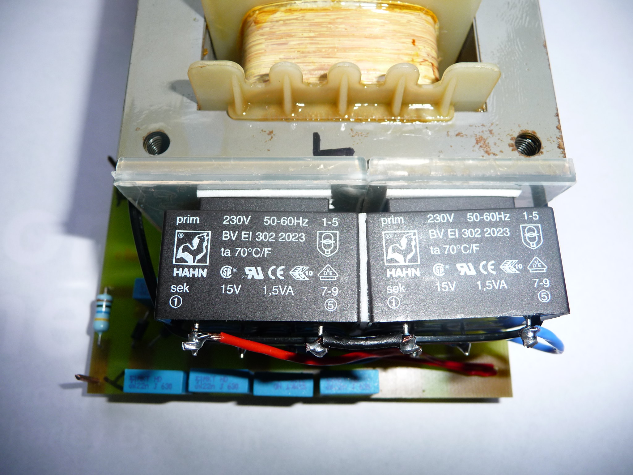 I left the traffos on for about 3/4 hour and then tested them again - the output was slightly less at 300V. Both traffos were super cool  I am now waiting for two more traffos to come - they should be here by the end of the week? Then I suppose more testing is required. That is another problem, my multimeter is only a cheap one that I bought ages ago which will not be up to the job. What so you think to this one cpc.farnell.com/tenma/72-9385/multimeter-digital-2ma-20a/dp/IN06233?ost=IN06233and will I need a high voltage probe like this one? www.rapidonline.com/Test-Measurement/High-Voltage-Multimeter-Probe-85-2216Cheers Frans |
|
solderdude
Administrator
measureutternutter
Posts: 4,887
|
Post by solderdude on Aug 10, 2015 19:05:00 GMT
That multimeter will do fine.
You won't need the HV probe (more suitable for old CRT monitors/TV's)
You can measure the indivudual sections as the input R = 20M Ohm and you can measure up to 1000V.
Each section will be lower than 1000V so it's just a matter of adding the voltages of each section (a section = 2 diodes and 2 caps)
Measure across C4 and C5 and C6 and C10 and add those voltages to calculate the bias voltage.
|
|
Crispy
very active
Madrigal music is playing - Voices can faintly be heard, "Please leave this patient undisturbed."
Posts: 779 
|
Post by Crispy on Aug 14, 2015 12:44:57 GMT
That multimeter will do fine. You won't need the HV probe (more suitable for old CRT monitors/TV's) You can measure the indivudual sections as the input R = 20M Ohm and you can measure up to 1000V. Each section will be lower than 1000V so it's just a matter of adding the voltages of each section (a section = 2 diodes and 2 caps) Measure across C4 and C5 and C6 and C10 and add those voltages to calculate the bias voltage. My new multimeter arrived today Frans, so I can get on with some measurements - the new transformers have not arrived yet though  I still have plenty of work to do so no big deal. I will let you know the mesurements as soon as I get them  |
|
Crispy
very active
Madrigal music is playing - Voices can faintly be heard, "Please leave this patient undisturbed."
Posts: 779 
|
Post by Crispy on Aug 14, 2015 19:48:05 GMT
Frans, below is the mesurements I took today after I let the traffos settle for 5 minutes. 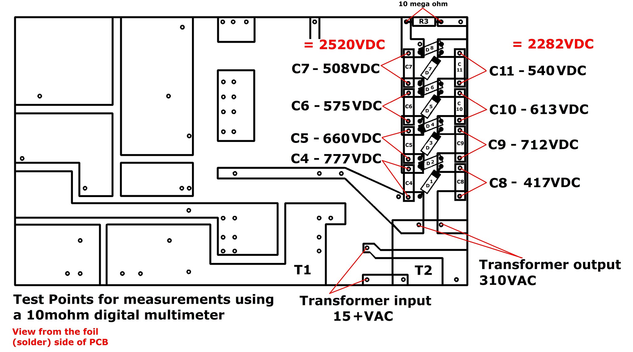 It looks like it is just a bit short of the required 2800VDC Is it now a case of adding 2 more caps & diodes? |
|
solderdude
Administrator
measureutternutter
Posts: 4,887
|
Post by solderdude on Aug 14, 2015 21:01:29 GMT
2500V is already a quite decent bias voltage.
Adding half section will give about 2800V and 1 full section about 3000V.
Before adding sections I would check to see if the audio trafos are still O.K.
You can do this by applying about 1V AC (tone generator or generated by a PC ?) 440Hz or 1kHz tone via an amplifier to the speaker input.
Then measure the AC voltage across the outer pins of the stators (without the stators attached, mains voltage OFF)
When both channels show about the same AC voltage (I expect between 25 and 50V AC) ? you will know the electronics are O.K.
Then it becomes time to check the drivers....
|
|
Crispy
very active
Madrigal music is playing - Voices can faintly be heard, "Please leave this patient undisturbed."
Posts: 779 
|
Post by Crispy on Aug 15, 2015 19:01:21 GMT
2500V is already a quite decent bias voltage. Adding half section will give about 2800V and 1 full section about 3000V. As I know nothing about this sort of thing what do you suggest is my best option? What difference would 3000V make over 2500V? Before adding sections I would check to see if the audio trafos are still O.K. You can do this by applying about 1V AC (tone generator or generated by a PC ?) 440Hz or 1kHz tone via an amplifier to the speaker input. Then measure the AC voltage across the outer pins of the stators (without the stators attached, mains voltage OFF) When both channels show about the same AC voltage (I expect between 25 and 50V AC) ? you will know the electronics are O.K. Then it becomes time to check the drivers.... Frans, can you put me a link up where I can download a free 440Hz test tone, I cant remember where I got my last 250Hz one from when I was matching up my AB box and I have been running around in circles on the web trying to find one.  Can I put the test tone on my SM6 and play it direct from there to my power amp and into the speaker input? Then how do I test the Audio traffo - by joining the White & Blue wires or do I test the white to ground then blue to ground? The other traffos arrived today and luckily I had the day off to fit them and repair the broken air core inductor (Thanks to Alan who gave me some inductor wire a long time ago) BTW Alan hows Neave - hope she is enjoying her summer holidays?) 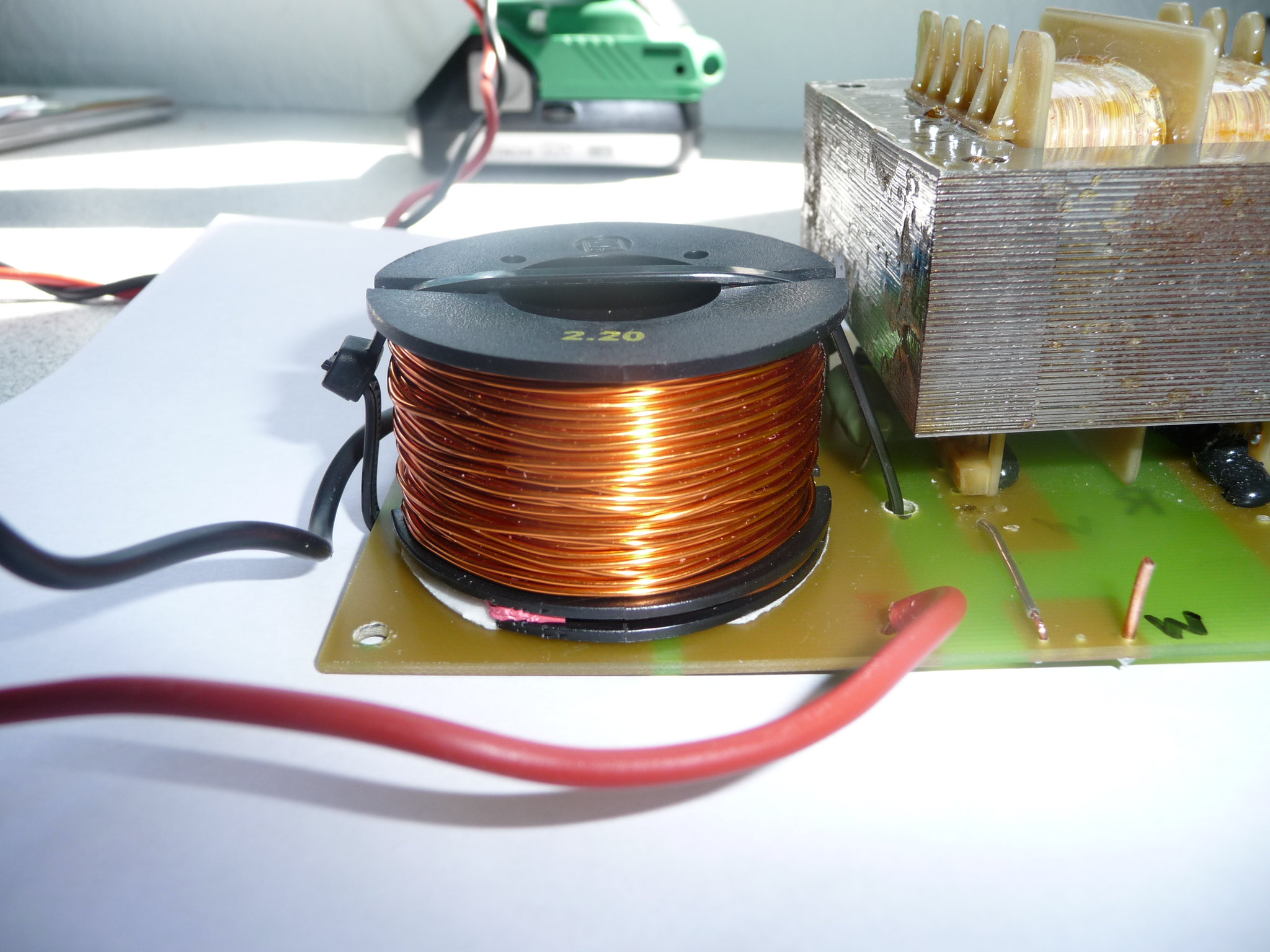 I also checked the voltages of the right amp and they are below and very similar the the left amp - but slightly lower. 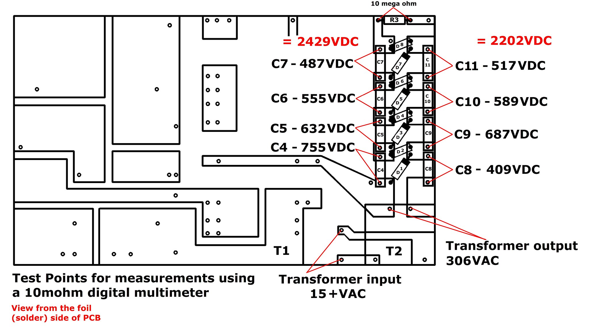 |
|
solderdude
Administrator
measureutternutter
Posts: 4,887
|
Post by solderdude on Aug 15, 2015 19:35:08 GMT
As I know nothing about this sort of thing what do you suggest is my best option? What difference would 3000V make over 2500V? On 3000V the stat will play slightly louder and as it needs to 'balance' with the woofer you can 'play' with the bias somewhat. Not too much as you run the risk of arcing or 'sticking'. On 3000V the stat will be around 1.5dB louder as when played from 2500V. Would try 2500 first though. Frans, can you put me a link up where I can download a free 440Hz test tone, I cant remember where I got my last 250Hz one from when I was matching up my AB box and I have been running around in circles on the web trying to find one.  just google 440Hz test tone download.. Can I put the test tone on my SM6 and play it direct from there to my power amp and into the speaker input? Anything that can play the tone will do (could be DAP, phone, laptop, tablet) Just connect the HP out to a power amplifier (make sure the volume is turned down !) Set the output voltage of the amp to 1V on your multimeter. Most meters have no problem reaching 440Hz. Then how do I test the Audio traffo - by joining the White & Blue wires or do I test the white to ground then blue to ground? Simply connect the amplifier to the speaker inputs (you may want to disconnect the woofer) Do NOT connect the stats power supply to mains ! Then put the measuring leads on the connector that connects to the stators. There are 3 pins. Connect the meter to the outer pins only (the middle one must not be measured this is for the 2500V DC bias only/ With the 440 Hz 1V tone you should get a 25V to 50V AC signal, perhaps even higher or lower. To be safe set the voltmeter in a 200V AC range or so. In any case ... the values for the left and right channel need to be very similar. Both DC voltages seem fine, the differences are too small to worry about. If this is O.K the stats themselves must be tested. |
|
Crispy
very active
Madrigal music is playing - Voices can faintly be heard, "Please leave this patient undisturbed."
Posts: 779 
|
Post by Crispy on Aug 17, 2015 17:28:41 GMT
Would try 2500 first though. Thats OK with me Frans, less work  Set the output voltage of the amp to 1V on your multimeter. Most meters have no problem reaching 440Hz. I don't quite get this bit Frans? I intend to measure both boards out of their enclosures with jumper wires with the the mains power & woofers disconected. see pic below: 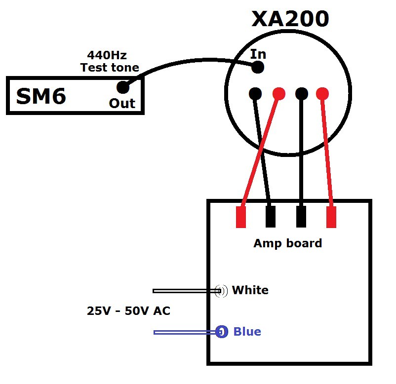 I just don't get what you mean by setting the amp to 1V on my MM? |
|