solderdude
Administrator
measureutternutter
Posts: 4,886
|
Post by solderdude on Jun 23, 2016 15:34:33 GMT
What the hell did I sent you ?
Can send the correct one .. do you have desoldering braid ?
|
|
Crispy
very active
Madrigal music is playing - Voices can faintly be heard, "Please leave this patient undisturbed."
Posts: 779 
|
Post by Crispy on Jun 23, 2016 19:58:24 GMT
|
|
solderdude
Administrator
measureutternutter
Posts: 4,886
|
Post by solderdude on Jun 23, 2016 20:30:46 GMT
That's the correct one.
You can also buy the parts from Conrad.
Maybe shipping is faster and or cheaper.
|
|
solderdude
Administrator
measureutternutter
Posts: 4,886
|
Post by solderdude on Jun 25, 2016 16:11:56 GMT
The 'in-line Kameleon' PCB has been designed.
Will be sent in for production next week or so.
By the end of July I may be having the first PCB working.
After that the much more time consuming job of creating a 'manual' for it.
This will probably take a month or 2 as well so expect it around September to be ready.
Perhaps Jeremy might also use this PCB but have it in a thicker and black PCB and the familiar G1217 look.
Seeing how busy he currently it may take many more months before it becomes a product.
This time ONLY 'big' through hole components, except for the filter modules which are SMD.
No wires or parts that have to be mounted on panels.
All parts are on the PCB so only some holes are needed in the front and rear as well as some modification of the metal work.
|
|
juke
very active
Posts: 396 
|
Post by juke on Jun 26, 2016 9:37:08 GMT
The 'in-line Kameleon' PCB has been designed. Will be sent in for production next week or so. By the end of July I may be having the first PCB working. What is it? I must have missed something. Syd |
|
Rabbit
Administrator
Posts: 7,091
|
Post by Rabbit on Jun 26, 2016 13:36:49 GMT
It has a line in and line out do that it can be put before your amp, and so be used with an Ember or Polaris!!!!
|
|
juke
very active
Posts: 396 
|
Post by juke on Jun 26, 2016 16:54:33 GMT
Thanks Ian, that threw me completely, I started thinking of the original one that Frans built into a headphone plug.
Brain is addled for sure.
Syd
|
|
Rabbit
Administrator
Posts: 7,091
|
Post by Rabbit on Jun 26, 2016 19:59:34 GMT
It'll be interesting when you think about it ..... An eq'd signal going into a hybrid amp like the Ember or an amp that emulates tubes in the case of the Polaris. Like putting a perfect signal in so that you're left with the pure 'essence' of the amp with much less headphone colouration to smear the amp flavour!!!!  |
|
|
|
Post by tunkejazz on Jun 27, 2016 4:53:31 GMT
The 'in-line Kameleon' PCB has been designed. Will be sent in for production next week or so. By the end of July I may be having the first PCB working. After that the much more time consuming job of creating a 'manual' for it. This will probably take a month or 2 as well so expect it around September to be ready. Perhaps Jeremy might also use this PCB but have it in a thicker and black PCB and the familiar G1217 look. Seeing how busy he currently it may take many more months before it becomes a product. This time ONLY 'big' through hole components, except for the filter modules which are SMD. No wires or parts that have to be mounted on panels. All parts are on the PCB so only some holes are needed in the front and rear as well as some modification of the metal work. Very looking forward to get my hands in one of these...please keep us posted! |
|
|
|
Post by mowglikun on Jul 4, 2016 16:34:42 GMT
The 'in-line Kameleon' PCB has been designed. Will be sent in for production next week or so. By the end of July I may be having the first PCB working. After that the much more time consuming job of creating a 'manual' for it. This will probably take a month or 2 as well so expect it around September to be ready. Perhaps Jeremy might also use this PCB but have it in a thicker and black PCB and the familiar G1217 look. Seeing how busy he currently it may take many more months before it becomes a product. This time ONLY 'big' through hole components, except for the filter modules which are SMD. No wires or parts that have to be mounted on panels. All parts are on the PCB so only some holes are needed in the front and rear as well as some modification of the metal work. Hi Frans. I was wondering if the final filter module would have a bypass switch, so that the amp following it can be used as a pre-amp for speakers without the headphone correction. |
|
jello
extremely active
Posts: 1,569
|
Post by jello on Jul 4, 2016 19:33:02 GMT
Hi Frans. I was wondering if the final filter module would have a bypass switch, so that the amp following it can be used as a pre-amp for speakers without the headphone correction. It will. Frans mentioned it recently in this thread: diyah.boards.net/thread/1319/opinions-on-switches |
|
|
|
Post by mowglikun on Jul 4, 2016 20:19:58 GMT
Nice! I was positive it would be included. |
|
Crispy
very active
Madrigal music is playing - Voices can faintly be heard, "Please leave this patient undisturbed."
Posts: 779 
|
Post by Crispy on Jul 13, 2016 20:05:17 GMT
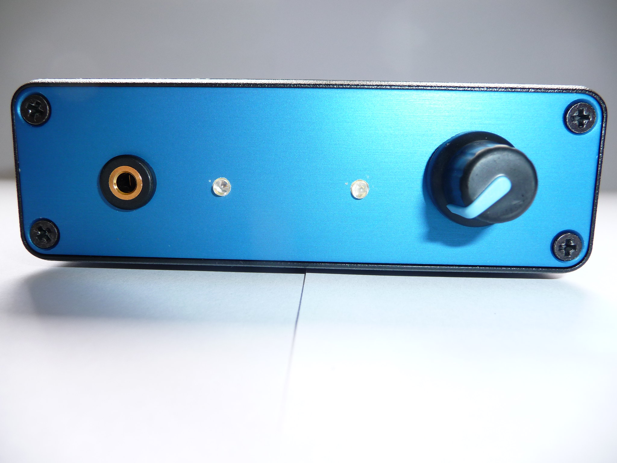
The rest of the components have arrived and I have now soldered them in place all but IC1, IC101 & IC102. So it is now time to test out the charging circuit  Frans, can I test this circuit with the board out of the unit? The reason I am asking this is that if all is Ok out of the unit, it will then be easier to solder the rest if the IC's in place whilst the board is out? The manual says test the V+ & V- test points - is this where the battery leads go? Kameleon almost finished?  My arrangement of the front panel - just awaiting the decals if they turn out OK  |
|
solderdude
Administrator
measureutternutter
Posts: 4,886
|
Post by solderdude on Jul 24, 2016 19:19:29 GMT
You can test the board out of the enclosure.
The test point V- is located between C15 and C20 (marked CON13 there is a - symbol in the copper plane)
The test point V+ is located between C12 and C21 (marked CON11 there is a + symbol in the copper plane)
The black test lead goes on CON12 (marked GND) between C13 and C14.
When you have a +9V on CON11 and a -9V on CON13 it is O.K.
When the battery voltage is below 14V the power supply voltage should switch off (takes a while as the capacitors need to discharge) then it is time to solder on the audio IC's.
the +/-9V is ofcourse not exactly 9V but half of the added battery voltage of both batteries.
You can quick test for a low battery voltage by removing 1 of the batteries and connect the + and - connections of the now open (as the battery is removed) battery cap.
This way the input voltage is 9V and the red LED on the front should be on and the +/- test point voltage should be close to 0 instead of +/- 4.5V
When the red LED goes on and there is a constant +/-4.5V there is something wrong with the MOSFET.
|
|
Crispy
very active
Madrigal music is playing - Voices can faintly be heard, "Please leave this patient undisturbed."
Posts: 779 
|
Post by Crispy on Jul 25, 2016 20:09:32 GMT
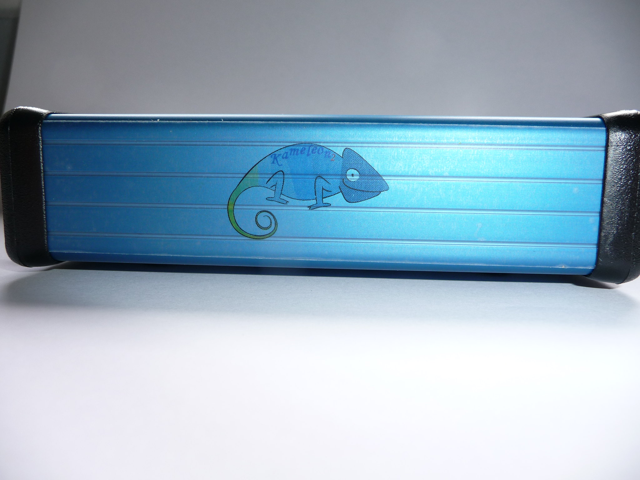
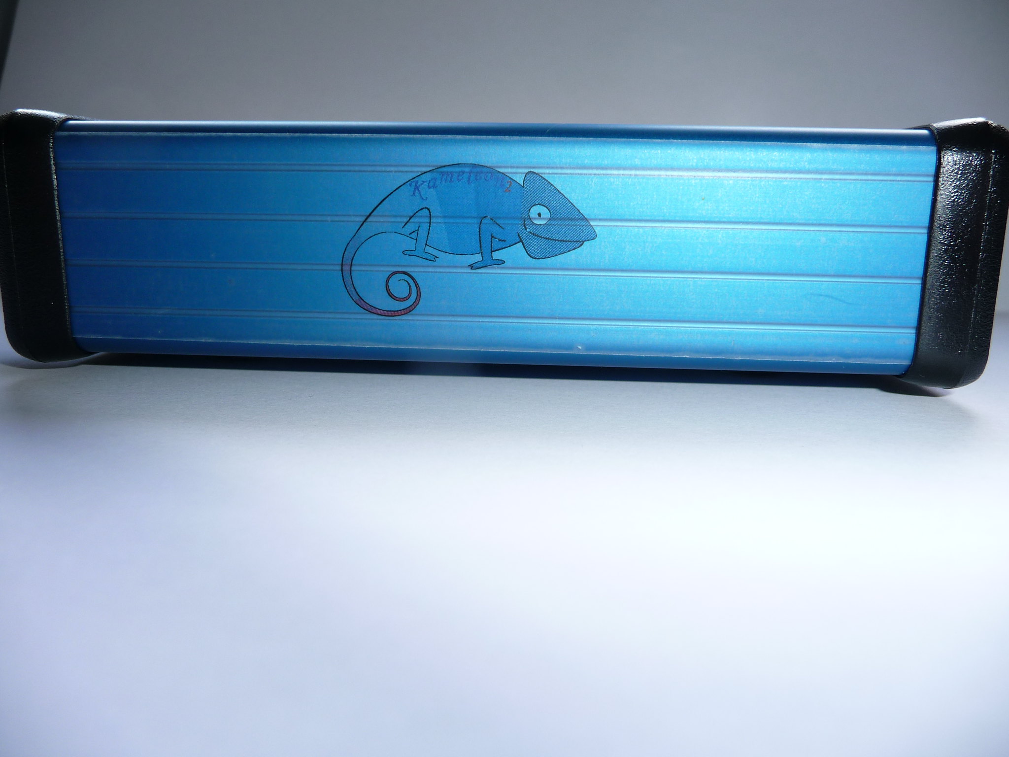
You can test the board out of the enclosure. The test point V- is located between C15 and C20 (marked CON13 there is a - symbol in the copper plane) The test point V+ is located between C12 and C21 (marked CON11 there is a + symbol in the copper plane) The black test lead goes on CON12 (marked GND) between C13 and C14. When you have a +9V on CON11 and a -9V on CON13 it is O.K. When the battery voltage is below 14V the power supply voltage should switch off (takes a while as the capacitors need to discharge) then it is time to solder on the audio IC's. the +/-9V is ofcourse not exactly 9V but half of the added battery voltage of both batteries. You can quick test for a low battery voltage by removing 1 of the batteries and connect the + and - connections of the now open (as the battery is removed) battery cap. This way the input voltage is 9V and the red LED on the front should be on and the +/- test point voltage should be close to 0 instead of +/- 4.5V When the red LED goes on and there is a constant +/-4.5V there is something wrong with the MOSFET. Thanks Frans, I hope you had a great holiday? I have just been looking at the board and found the test points that you mentioned - I just need to find a spare hour to actually test it now  I had a play about with some decals and was not too impressed, the front panel was absolute dog T**d and that went straight in the bin, the side ones are a little better and I am going to leave them in place for now, but I can see them coming off when the amp is finished. This side the kameleon's tail changes from green to blue:  This side the kameleon's tail changes from red to blue: the red you can hardly see.  |
|